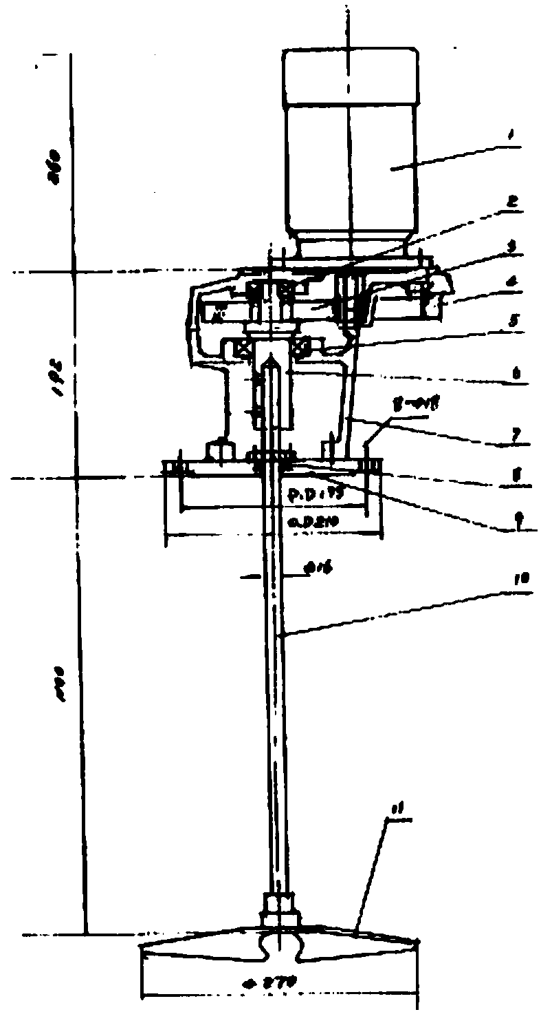
Vertical stirrer
A vertical mixer and mixer technology, which is applied to mixer accessories, mixers with rotary mixing devices, mixers, etc., can solve the problems of increasing costs, increasing equipment footprint, and inconvenient operation, and reducing dynamic loads. and static load, high weight, low cost effect
- Summary
- Abstract
- Description
- Claims
- Application Information
AI Technical Summary
Problems solved by technology
Method used
Image
Examples
Embodiment approach 1
[0011] A vertical mixer of the present invention includes a motor 1, a first bearing 2, a gear set 3, a gear box 4, a second bearing 5, a transmission shaft 6, a frame 7, a seal 8, a chassis flange 9, a stirring shaft 10, and an impeller 11; where:
[0012] The motor 1 is installed on the upper side of the frame 7; the chassis flange 9 is installed on the lower side of the frame 7;
[0013] The first bearing 2, the gear set 3, the gear box 4, the second bearing 5, and the transmission shaft 6 are all installed inside the frame 7; the transmission shaft 6 is fixed on the frame by the first bearing 2 and the second bearing 5 In the frame 7; the stirring shaft 10 is connected with the transmission shaft 6; the impeller 11 is installed at one end of the stirring shaft 10; the output shaft of the motor 1 is connected with the pinion main shaft of the gear set 3; the chassis flange 9 Between the stirring shaft 10 is a seal 8.
[0014] The seal 8 is an oil seal.
Embodiment approach 2
[0016] A vertical mixer of the present invention includes a motor 1, a first bearing 2, a gear set 3, a gear box 4, a second bearing 5, a transmission shaft 6, a frame 7, a seal 8, a chassis flange 9, a stirring shaft 10, and an impeller 11; where:
[0017] The motor 1 is installed on the upper side of the frame 7; the chassis flange 9 is installed on the lower side of the frame 7;
[0018] The first bearing 2, the gear set 3, the gear box 4, the second bearing 5, and the transmission shaft 6 are all installed inside the frame 7; the transmission shaft 6 is fixed on the frame by the first bearing 2 and the second bearing 5 In the frame 7; the stirring shaft 10 is connected with the transmission shaft 6; the impeller 11 is installed at one end of the stirring shaft 10; the output shaft of the motor 1 is connected with the pinion main shaft of the gear set 3; the chassis flange 9 Between the stirring shaft 10 is a seal 8.
[0019] The seal 8 is a packing seal.
PUM
 Abstract
Description
Claims
Application Information
 - R&D
- Intellectual Property
- Life Sciences
- Materials
- Tech Scout
- Unparalleled Data Quality
- Higher Quality Content
- 60% Fewer Hallucinations
Browse by: Latest US Patents, China's latest patents, Technical Efficacy Thesaurus, Application Domain, Technology Topic, Popular Technical Reports.
© 2025 PatSnap. All rights reserved.Legal|Privacy policy|Modern Slavery Act Transparency Statement|Sitemap|About US| Contact US: help@patsnap.com

