Parking interlock device for an automotive transmission

a technology for interlocking devices and automotive transmissions, which is applied in mechanical devices, braking systems, transportation and packaging, etc., can solve problems such as annoying scattering, dynamic damage to components, and impulse exerted on the parking lock pawl during ratcheting, so as to reduce the dynamic loading of parking locks. , the effect of constant impuls

Active Publication Date: 2012-04-26
ZF FRIEDRICHSHAFEN AG
View PDF2 Cites 10 Cited by
  • Summary
  • Abstract
  • Description
  • Claims
  • Application Information

AI Technical Summary

Benefits of technology

[0005]The purpose of the present invention, with a parking lock device of the type mentioned at the beginning, is to achieve as gentle and material-sparing rejection as possible of the locking pawl above the drop-in speed and up to higher vehicle speeds, and thus to reduce the impact loading of the locking pawl that takes place during ratcheting.
[0007]The invention provides for a linear relationship between the pivot angle of the parking lock pawl and the rotational angle of the parking lock gearwheel, so that the pivoting speed of the parking lock pawl is constant. By contrast with the type-defining prior art, during ratcheting an impulse exerted on the parking lock pawl in the contact area of the crown contours of the pawl tooth and the tooth crown of the parking lock gearwheel is consequently independent of the exact point of contact. In this case the value of the pivoting speed, i.e. the change of pivoting angle, is a measure of the impulse. Thanks to the constant impulse on the parking lock pawl, the impact response during ratcheting, i.e. the loading of the components, is also reduced.
[0013]In a further preferred embodiment the crown tip relief is composed of a fraction for the wheel and a fraction for the pawl, such that the fractions preferably behave as the tooth widths of the wheel teeth and the pawl tooth. In this way the linear kinematic behavior is maintained throughout the contact area during the contact of the teeth, i.e. with a constant impulse and reduced dynamic loading of the parking lock.
[0015]According to a further embodiment the radius of the circular arc forming the first and / or the second contour is in a range from 0.8 up to 1.2 times the outer radius of the parking lock gearwheel. In particular, the radius of the circular arc contour is equal to the outer radius of the parking lock gearwheel, i.e. the mid-point of the contour circle is in the area of and offset relative to the rotational axis of the parking lock gearwheel. A curvature radius for the first and / or second contour with this order of magnitude results in a relatively small, constant impulse, i.e. reduced dynamic loading of the parking lock.

Problems solved by technology

The rejection of the locking pawl above the drop-in speed is known as “ratcheting” and, depending on the tooth geometry, results in a dynamic that damages the components.
Disadvantageously, however, the impulse exerted on the parking lock pawl during ratcheting depends very much on the exact position of the contact point at which the pawl tooth of the parking lock pawl meets a tooth of the parking lock gearwheel.
The resulting scatter can be perceived by the driver of the vehicle as annoying.

Method used


Image

  • Parking interlock device for an automotive transmission
  • Parking interlock device for an automotive transmission
  • Parking interlock device for an automotive transmission

Examples


Embodiment Construction

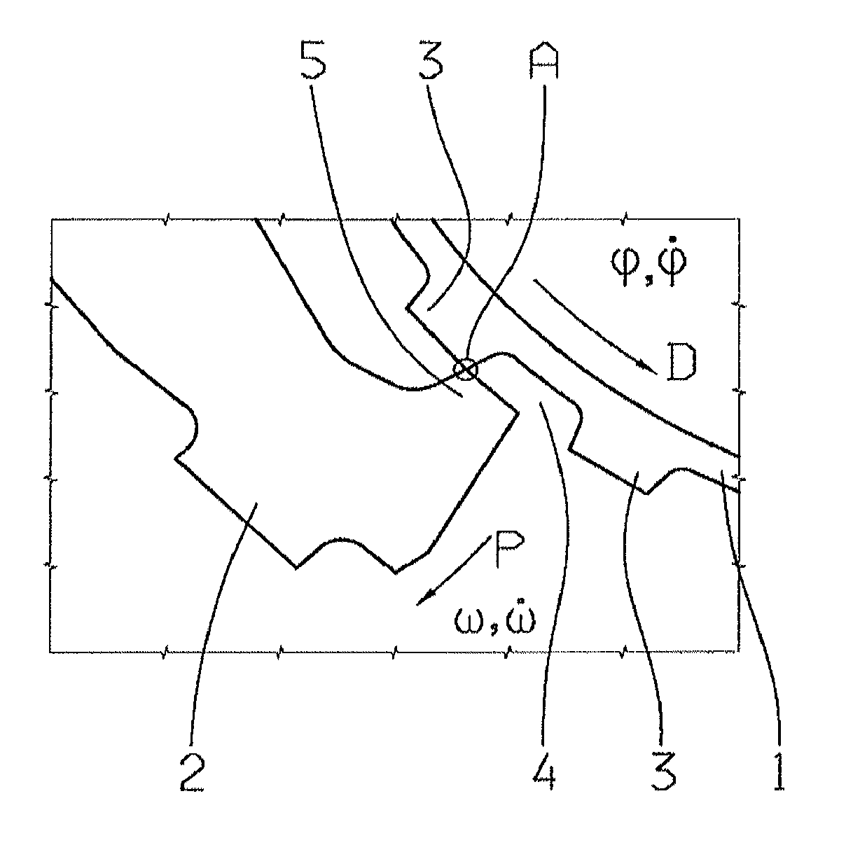
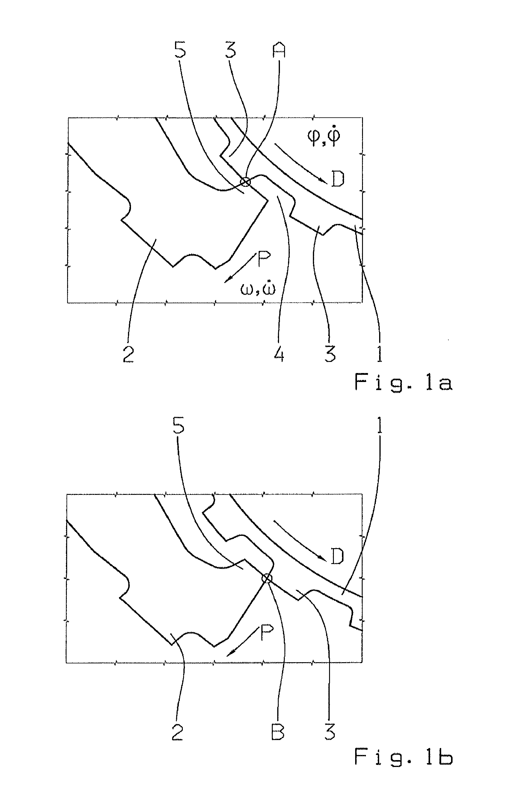
[0027]FIGS. 1a and 1b show two positions of contact between a parking lock gearwheel 1 and a parking lock pawl 2 of a parking lock device (not shown in full), which can be used for example for an automatic transmission or even a dual-clutch transmission of a motor vehicle. As is known, the parking lock device serves to lock a transmission output shaft (not shown) mechanically, in order to prevent the vehicle from rolling away. The parking lock gearwheel 1 is connected to the transmission output shaft (not shown) in a rotationally fixed manner and undergoes rotational movement in the direction of the arrow D with a rotational angle φ and a rotational speed φ-dot (φ). The parking lock pawl 2 is mounted to pivot in a transmission housing (not shown) and, when the two tooth crowns rest against one another, undergoes a pivoting movement in the direction of the arrow P with the pivoting angle ω and the pivoting speed ω-dot (ω). The parking lock gearwheel 1, also referred to in what follow...


PUM


Abstract

A transmission parking lock device comprising a gearwheel with teeth and gaps and a pawl having a pawl tooth. The gearwheel rotates and the pawl pivots about axes that are parallel to each other. The gearwheel teeth each have a first contour and tooth flanks with respect to rotation of the gearwheel. The pawl tooth has a second contour and tooth flanks relative to the rotation of the gearwheel, and the gearwheel has an outer radius. The gearwheel and pawl are kinematically linked by a linear relationship between the pivoting and rotational angles. The first and / or second contour are at least partially circular with a radius of the outer radius of the gearwheel, and the teeth and / or the pawl tooth have, in the area of the front tooth flank of the gearwheel or parking lock pawl, a crown tip relief relative to the outer radius of the gearwheel.

Description

[0001]This application claims priority from German patent application serial no. 10 2010 042 917.1 filed Oct. 26, 2010.FIELD OF THE INVENTION[0002]The invention concerns a parking lock device for an automotive transmission.BACKGROUND OF THE INVENTION[0003]Parking locks, which are designed to prevent a motor vehicle with an automatic transmission from inadvertently rolling away, are subject to various criteria, among which in particular a rejection condition at higher vehicle speeds must be fulfilled. In general a parking lock is designed for a particular drop-in speed, i.e. a limit speed of the vehicle at which the locking pawl can still just drop into a tooth gap so that the locked position is reached. Above this limit speed it must be ensured that the pawl tooth does not drop into a tooth gap, but is kept out by virtue of the teeth or tooth contour. The rejection of the locking pawl above the drop-in speed is known as “ratcheting” and, depending on the tooth geometry, results in a...

Claims


Application Information

Patent Timeline
Patent Type & Authority Applications(United States)
IPC IPC(8): B60T1/06
CPCY10T74/2137F16H63/3425
Inventor AUSTERMANN, BERNDMILLER, TOBIASLIST, MATTHIASKATZORECK, KARL-HERMANNBREITWEG, THOMASRASCH, ARMIN
Owner ZF FRIEDRICHSHAFEN AG
Why Eureka
Try Eureka