

Dust removal device for electrical automation equipment
A technology of electrical automation and dust removal device, which is applied in the direction of dust removal, transportation and packaging, cleaning methods and utensils, etc. It can solve problems such as poor use effect, affecting cleaning effect, and precision electrical components cannot be cleaned separately, so as to avoid secondary First attachment, guaranteed cleaning effect, and good use effect
- Summary
- Abstract
- Description
- Claims
- Application Information
AI Technical Summary
Problems solved by technology
Method used
Image

Examples
Embodiment 1
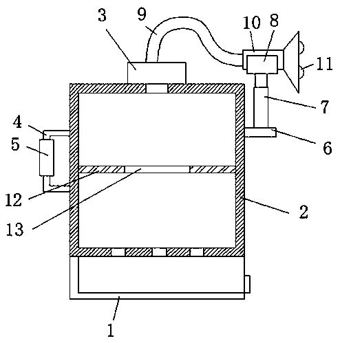
[0021] refer to figure 1 , a dust removal device for electrical automation equipment, comprising a base 1, the top of the base 1 is fixedly connected to a dust collection box 2, the top of the dust collection box 2 is fixedly connected to a dust suction fan 3, and one side of the dust collection box 2 is symmetrically fixedly connected to a handle frame 4. The handle frame 4 is covered with a non-slip sleeve 5, the other side of the dust collection box 2 is fixedly connected with a connecting plate 6, the top of the connecting plate 6 is fixedly connected with an electric push rod 7, and the top of the electric push rod 7 is fixedly connected with a clamp 8 , the top of the dust suction fan 3 is fixedly connected with a conveying leather tube 9, and one end of the conveying leather tube 9 is fixedly connected with a dust collection cover 10 on the fixture 8, and the inside of the dust collection cover 10 is symmetrically rotated and connected with a dust removal roller 11, and ...
Embodiment 2
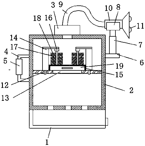
[0028] refer to figure 2 , a dust removal device for electrical automation equipment, comprising a base 1, the top of the base 1 is fixedly connected to a dust collection box 2, the top of the dust collection box 2 is fixedly connected to a dust suction fan 3, and one side of the dust collection box 2 is symmetrically fixedly connected to a handle frame 4. The handle frame 4 is covered with a non-slip sleeve 5, the other side of the dust collection box 2 is fixedly connected with a connecting plate 6, the top of the connecting plate 6 is fixedly connected with an electric push rod 7, and the top of the electric push rod 7 is fixedly connected with a clamp 8 , the top of the dust suction fan 3 is fixedly connected with a conveying leather tube 9, and one end of the conveying leather tube 9 is fixedly connected with a dust collection cover 10 on the fixture 8, and the inside of the dust collection cover 10 is symmetrically rotated and connected with a dust removal roller 11, and...
PUM
 Abstract
Description
Claims
Application Information