
A large degree of freedom arc surface support base driving structure for an automated welding manipulator

An automatic welding technology with a large degree of freedom, applied in welding equipment, auxiliary welding equipment, welding/cutting auxiliary equipment, etc., can solve the problem of inconvenient quick alignment and position adjustment of components, inconvenient use of large-scale adjustment and change of angle, component Problems such as the influence of mechanical welding efficiency, to achieve the effect of convenient adjustment and change of application, accurate and convenient positioning, and stable positioning

Active Publication Date: 2021-06-11
威海众合机电科技有限公司
View PDF6 Cites 0 Cited by
  • Summary
  • Abstract
  • Description
  • Claims
  • Application Information

AI Technical Summary

Problems solved by technology

[0007] The purpose of the present invention is to provide a large-degree-of-freedom arc surface support base drive structure for an automated welding manipulator, to solve the above-mentioned background technology. It is inconvenient to adjust and change the use angle of the existing automatic welding manipulator support base drive structure. , so that the movement angle range is small when rotating and used, and the range is limited when the components are positioned and moved, which is inconvenient for quick alignment and position adjustment between components, which affects the mechanical welding efficiency of the components and affects the mechanical welding. When the work is carried out normally, when the position of the manipulator is moved as a whole, the movement limit operation of the base during the use of the manipulator is prone to unstable placement. Long-term work will cause the manipulator to clamp and position the components and affect the welding work. The stability of time leads to the problem of deviation in the accuracy of welding positioning

Method used


Image

  • A large degree of freedom arc surface support base driving structure for an automated welding manipulator
  • A large degree of freedom arc surface support base driving structure for an automated welding manipulator
  • A large degree of freedom arc surface support base driving structure for an automated welding manipulator

Examples


Embodiment Construction

[0026] The following will clearly and completely describe the technical solutions in the embodiments of the present invention with reference to the accompanying drawings in the embodiments of the present invention. Obviously, the described embodiments are only some, not all, embodiments of the present invention. Based on the embodiments of the present invention, all other embodiments obtained by persons of ordinary skill in the art without making creative efforts belong to the protection scope of the present invention.

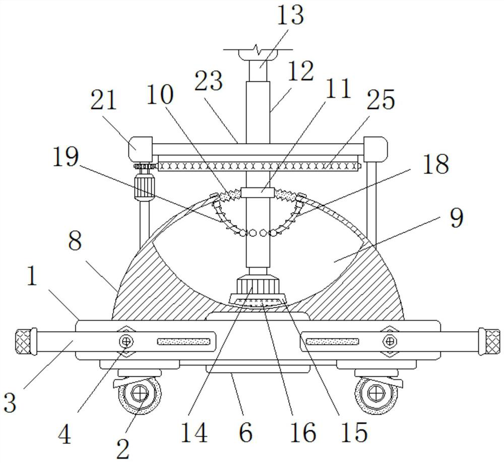
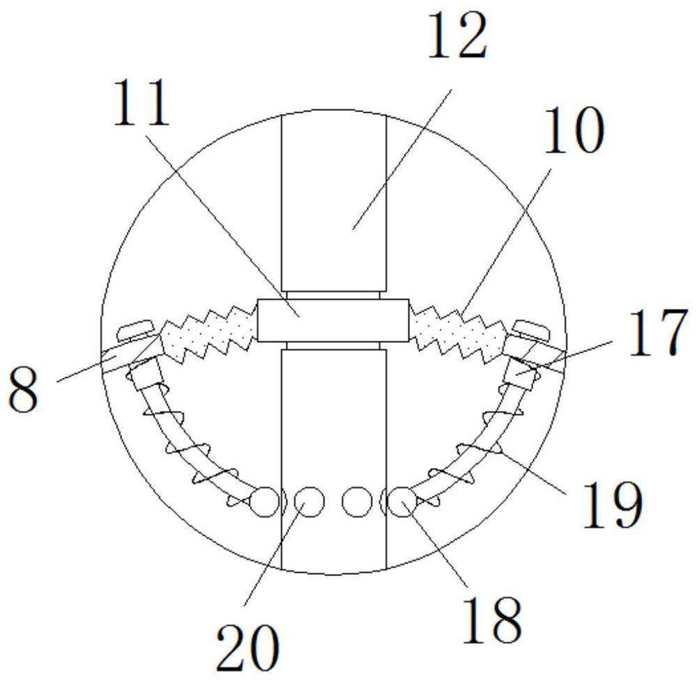
[0027] see Figure 1-6 , the present invention provides a technical solution: a large-degree-of-freedom arc surface support base drive structure for an automated welding manipulator, including a bottom plate 1, a universal wheel assembly 2, a positioning support 3, a rotating rod 4, a worm wheel 5, and a first motor 6 , worm 7, base 8, positioning cavity 9, reinforcing rib 10, positioning ring 11, outer tube 12, connecting inner rod 13, second motor 14, protec...


PUM


Abstract

The invention discloses a large-degree-of-freedom arc surface supporting base driving structure for an automatic welding manipulator, which includes a bottom plate, a first motor, a second motor, an electromagnet, an electrified slip ring, an electric telescopic rod and a third motor. A universal wheel assembly is fixedly installed at the edge of the bottom, the first motor is fixed inside the bottom plate, an outer tube runs through the middle of the positioning ring, a protective support is installed on the outer wall of the second motor, and the protective support An electromagnet is fixed on the bottom of the seat, a sliding pipe is fixed on the edge of the connection between the base and the reinforcing rib, an outer bracket is installed on the outer wall of the base, and the third motor is installed on the outer bracket. The driving structure of the large-degree-of-freedom arc-surface supporting base of the automated welding manipulator can change the high-freedom angle turning motion of the manipulator, improve the practicability of the manipulator clamping application, and facilitate the use and positioning of the base, making its working position more stable with precision.

Description

technical field [0001] The invention relates to the technical field of automation machinery, in particular to a driving structure for a large-degree-of-freedom curved surface support base of an automation welding manipulator. Background technique [0002] Automated machinery is a technical application of modern machinery. Through the use of automated machinery, the production efficiency and quality of the industry can be improved, modern scientific production can be realized, the consumption of labor force can be reduced, the hands of laborers can be liberated, and the economic production of the industry can be improved. Speed ​​provides new blood for the rapid development of the industry. In the automatic application of the welding process in mechanical processing, in order to facilitate the welding work and facilitate the welding alignment between large object components, it is necessary to use welding manipulators for auxiliary installation of components Positioning is co...

Claims


Application Information

Patent Timeline
Patent Type & Authority Patents(China)
IPC IPC(8): B23K37/04
CPCB23K37/04
Inventor 陈英
Owner 威海众合机电科技有限公司
Learn More