Device and method for calibrating shot blasting position of shot blasting machine

A technology of calibration device and calibration method, which is applied in the direction of explosion generation device, used abrasive processing device, spray gun, etc., can solve the problems of programming position change, not considering the influence of nozzle bracket assembly clearance, etc., to achieve accurate calibration and avoid spraying Insufficient pill coverage and the effect of ensuring accuracy

Active Publication Date: 2020-02-21
AECC AVIATION POWER CO LTD
View PDF6 Cites 1 Cited by
  • Summary
  • Abstract
  • Description
  • Claims
  • Application Information

AI Technical Summary

Problems solved by technology

[0002] In the existing shot blasting process, due to equipment maintenance, replacement of the spray gun and bracket system, or special circumstances such as gun collision during shot peening experiments, it is necessary to re-adjust and reset the spray gun, and each adjustment and reset depends on the mechanical function of the equipment. It is realized by returning to zero, without considering the influence of assembly clearances such as nozzle brackets
This will cause the nozzle position to change from the originally programmed position

Method used


Image

  • Device and method for calibrating shot blasting position of shot blasting machine
  • Device and method for calibrating shot blasting position of shot blasting machine
  • Device and method for calibrating shot blasting position of shot blasting machine

Examples


Embodiment Construction

[0041] In order to enable those skilled in the art to better understand the solutions of the present invention, the following will clearly and completely describe the technical solutions in the embodiments of the present invention in conjunction with the drawings in the embodiments of the present invention. Obviously, the described embodiments are only It is an embodiment of a part of the present invention, but not all embodiments. Based on the embodiments of the present invention, all other embodiments obtained by persons of ordinary skill in the art without making creative efforts shall fall within the protection scope of the present invention.

[0042] It should be noted that the terms "first" and "second" in the description and claims of the present invention and the above drawings are used to distinguish similar objects, but not necessarily used to describe a specific sequence or sequence. It is to be understood that the data so used are interchangeable under appropriate ...


PUM


Abstract

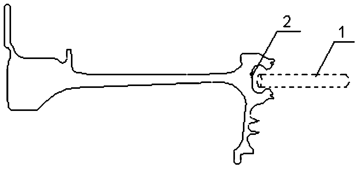
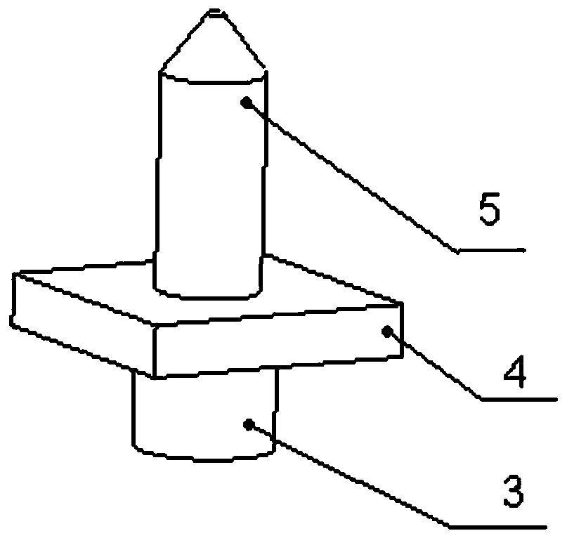
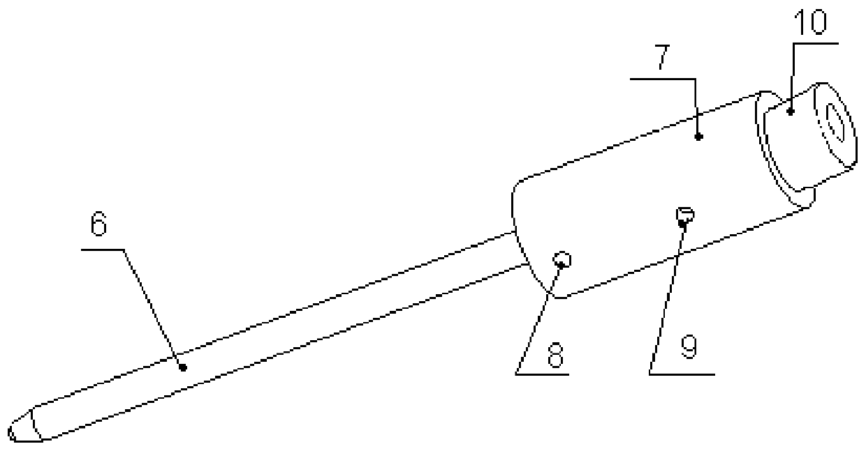
The invention discloses a device and method for calibrating the shot blasting position of a shot blasting machine. The device comprises a calibration block and a calibration simulation gun used for simulating a shot blasting path. Connection ends and calibration ends are arranged on the calibration block and the calibration simulation gun. The connection end of the calibration block is connected with a center positioning hole of a machine tool, and the connection end of the calibration simulation gun is connected with a nozzle of the shot blasting machine. When the shot blasting position of the shot blasting machine is calibrated, the calibration end of the calibration block and the calibration end of the calibration simulation gun are aligned. A conventional spray gun calibration manner is changed, a spray gun position calibration device is adopted for calibrating the position of the nozzle before shot blasting, thus, the quality defect that the shot blasting coverage rate is insufficient as the position of the nozzle is not precise during shot blasting is avoided, the movement track of the nozzle in the shot blasting process is precisely calibrated, and the one-time percent of pass of the shot blasting coverage rate is increased. Meanwhile, the device is simple in structure, convenient to produce and machine, low in cost and suitable for being used and popularized.

Description

technical field [0001] The invention belongs to the field of shot peening, and relates to a shot peening position calibration device and method of a shot peening machine. Background technique [0002] In the existing shot blasting process, due to equipment maintenance, replacement of the spray gun and bracket system, or special circumstances such as gun collision during shot peening experiments, it is necessary to re-adjust and reset the spray gun, and each adjustment and reset depends on the mechanical function of the equipment. It is realized by returning to zero, without considering the influence of the assembly clearance such as the nozzle bracket. This will cause the nozzle position to change from the originally programmed position. The change of the shot peening position has a great influence on the coverage of the part, especially in special positions such as small ring grooves and assembly holes, the accuracy of the position is very important. [0003] When peening...

Claims


Application Information

Patent Timeline
Patent Type & Authority Applications(China)
IPC IPC(8): B24C9/00B24C5/04
CPCB24C5/04B24C9/00
Inventor 张永刚高相毅石红敏杨立强柳培发段佩冯咏何亮
Owner AECC AVIATION POWER CO LTD
Why Eureka
Try Eureka