Composite material forming equipment

A technology of molding equipment and composite materials, applied in the direction of coating, the device for coating liquid on the surface, etc., can solve the problems of difficult unloading, hidden dangers, high labor costs, etc., to improve the degree of automation, improve production efficiency, The effect of improving safety

Inactive Publication Date: 2020-02-21
户玉珠
View PDF4 Cites 3 Cited by
  • Summary
  • Abstract
  • Description
  • Claims
  • Application Information

AI Technical Summary

Problems solved by technology

[0002] Composite materials are composed of two or more materials with different properties. Through physical or chemical methods, materials with new properties are formed macroscopically. Various materials learn from each other in terms of performance and produce synergistic effects. The overall performance is superior to the original constituent materials and meets various requirements. The matrix materials of composite materials are divided into two categories: metal and non-metal, but the production of composite materials is difficult, so a special automatic composite material forming equipment is required. , but with the development of science and technology, there are more and more types of composite material molding equipment, and their functions are becoming more and more powerful

Method used


Image

  • Composite material forming equipment
  • Composite material forming equipment
  • Composite material forming equipment

Examples


Example Embodiment

[0021] The present invention will be further explained below in conjunction with specific embodiments. Among them, the drawings are only used for exemplary description, and they are only schematic diagrams, rather than physical diagrams. They should not be understood as a limitation of the patent. In order to better illustrate the present invention DETAILED DESCRIPTION OF THE EMBODIMENTS Some components in the drawings may be omitted, enlarged or reduced, and do not represent the size of the actual product. For those skilled in the art, it is understandable that some well-known structures in the drawings and their descriptions may be omitted, based on The specific embodiments of the present invention, and all other specific embodiments obtained by those of ordinary skill in the art without creative work, fall within the protection scope of the present invention.

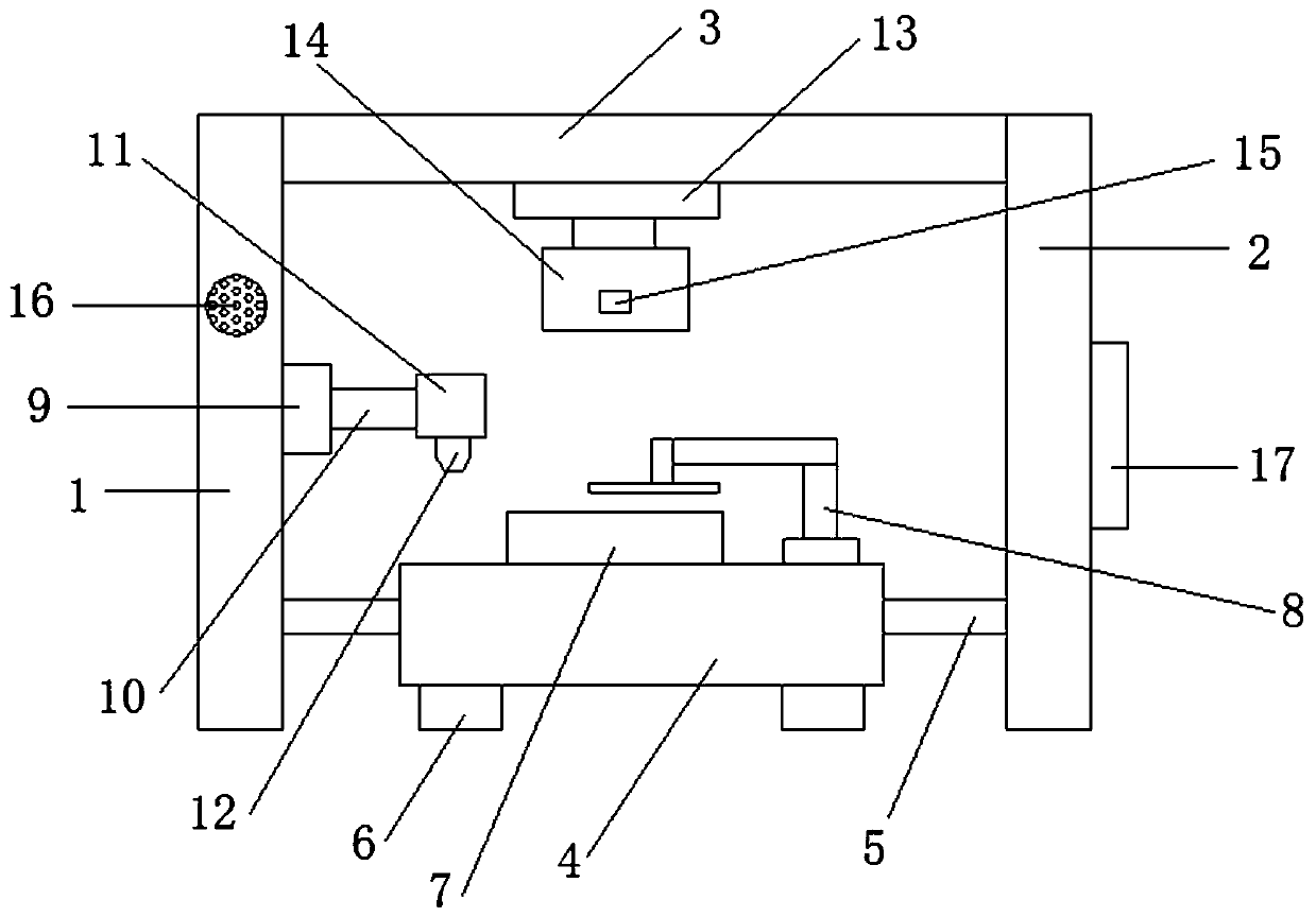
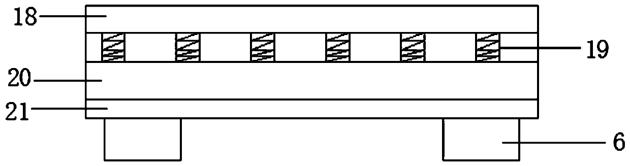
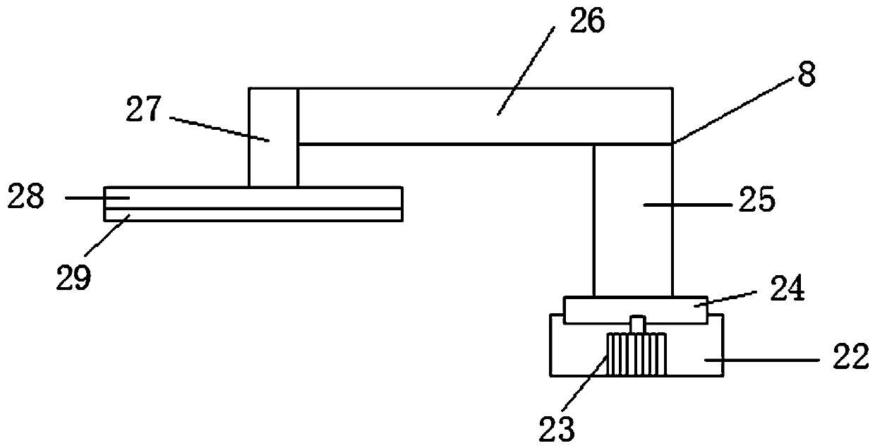
[0022] Such as Figure 1-4 As shown, a composite material molding equipment includes a first support frame 1, a secon...


PUM


Abstract

The invention relates to composite material forming equipment. The composite material forming equipment comprises a first supporting frame and a second supporting frame; the first supporting frame isarranged on the left side of the second supporting frame; a cross beam is fixedly connected between the first supporting frame and the second supporting frame, and is fixedly connected to the tops ofthe first supporting frame and the second supporting frame; the first supporting frame and the second supporting frame are fixedly connected with a supporting table through a reinforcing rod; supporting feet are fixedly connected to the bottom of the supporting table; the top of the supporting table is fixedly connected with a punching die table; a uniform applying device is arranged on the rightside of the punching die table; the right end of the first supporting frame is fixedly connected with a first hydraulic cylinder; the output end of the first hydraulic cylinder is fixedly connected with a first telescopic rod; and the right end of the first telescopic rod is fixedly connected with a glue storage box. The whole composite material forming equipment facilitates uniformly applying glue, rapid drying of the glue is facilitated, the automation degree of composite plate production is improved, the discharging after plate forming is facilitated, and the production efficiency is improved.

Description

technical field [0001] The invention relates to composite material molding equipment, which belongs to the technical field of molding equipment. Background technique [0002] Composite materials are composed of two or more materials with different properties. Through physical or chemical methods, materials with new properties are formed macroscopically. Various materials learn from each other in terms of performance and produce synergistic effects. The overall performance is superior to the original constituent materials and meets various requirements. The matrix materials of composite materials are divided into two categories: metal and non-metal, but the production of composite materials is difficult, so a special automatic composite material forming equipment is required. , but with the development of science and technology, there are more and more types of composite material molding equipment, and their functions are becoming more and more powerful, and they bring more a...

Claims


Application Information

Patent Timeline
IPC IPC(8): B29C65/72B29C65/56B29C65/48B05C5/02B05C11/02B05C9/14
CPCB05C5/0208B05C9/14B05C11/023B29C65/48B29C65/56B29C65/72
Inventor 户玉珠
Owner 户玉珠
Why Eureka
Try Eureka