
Driving, sensing and pipeline structure integrated leg of hydraulic driving foot type robot

A technology for driving feet and robots, which is applied in the direction of fluid pressure actuators, motor vehicles, mechanical equipment, etc. It can solve problems such as cylinder rod bending, pipeline extrusion, and foot force increase, so as to reduce its own weight, solve leakage and Tubing extrusion, effect of reducing complexity

Inactive Publication Date: 2020-02-21
SHANDONG UNIV
View PDF7 Cites 3 Cited by
  • Summary
  • Abstract
  • Description
  • Claims
  • Application Information

AI Technical Summary

Problems solved by technology

This will greatly increase the complexity of the robot's leg structure and its own weight.
[0003] When the hydraulically driven legged robot moves, the complicated oil pipes and pipelines will move together with the legs, which will not only affect the movement space of the robot legs, but also easily cause oil pipe leakage and pipeline extrusion, which increases the cost and cost of robot maintenance. burden
[0004] In addition, through experiments on the leg structure of the existing hydraulically driven legged robot, it was found that the plantar force directly acts on the cylinder rod of the hydraulic cylinder. Under the influence of uncertain factors, the plantar force increases, and the The force exceeds its strength limit, causing the cylinder rod to bend and unable to complete the telescopic action

Method used


Image

  • Driving, sensing and pipeline structure integrated leg of hydraulic driving foot type robot
  • Driving, sensing and pipeline structure integrated leg of hydraulic driving foot type robot
  • Driving, sensing and pipeline structure integrated leg of hydraulic driving foot type robot

Examples


Embodiment Construction

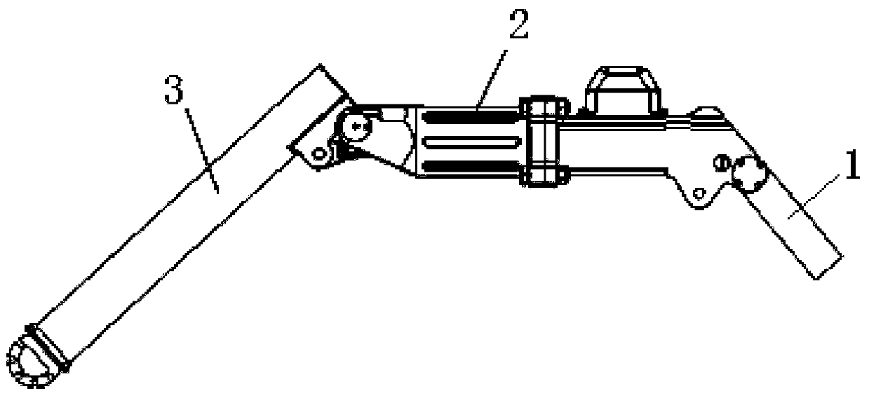
[0024] Such as figure 1 As shown, the present invention is oriented to the hydraulically driven legged robot with integrated legs for driving, sensing, piping, and structure, including a thigh rod 1, a housing 2 and a calf rod 3, and the thigh rod 1 and the housing 2 pass through the thigh The joint 10 is hinged, and the shell 2 and the calf rod 3 are hinged through the calf joint 4 .

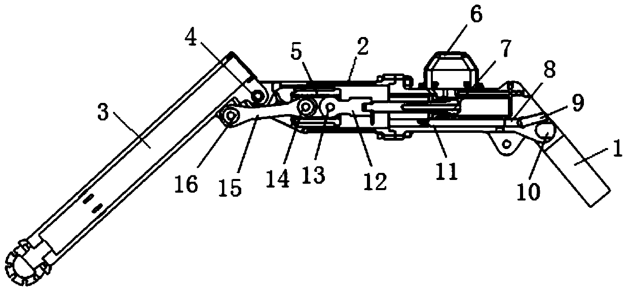
[0025] Such as figure 2 As shown, the mechanical leg housing 2 is provided with a graphite sliding sleeve 5 , the sliding sleeve 5 is slidingly connected to the mechanical leg housing 2 , and the sliding sleeve 5 can slide in the mechanical leg housing 2 . A hydraulic cylinder 7 is installed in the mechanical leg housing 2, the cylinder rod of the hydraulic cylinder 7 is connected to the force sensor 12, and the force sensor 12 is hinged to one end of the sliding sleeve 5 through the first hinge shaft 13, and the first hinge shaft 13 and the sliding sleeve 5 are Fixed connection. Metal conn...


PUM


Abstract

The invention discloses a driving, sensing and pipeline structure integrated leg of a hydraulic driving foot type robot. The leg comprises a thigh rod, a shell and a shank rod, wherein the thigh rod is hinged to the shell, and the shell is hinged to the shank rod; and a sliding sleeve and a hydraulic cylinder are arranged in the shell, a cylinder rod of the hydraulic cylinder is hinged to one endof the sliding sleeve, the shank rod is connected with the sliding sleeve through a connecting rod, and the two ends of the connecting rod are hinged to the sliding sleeve and the shank rod correspondingly. A force sensor is connected between the cylinder rod of the hydraulic cylinder and the sliding sleeve, and the two ends of the force sensor are hinged to the cylinder rod and the sliding sleeve. According to the leg, the hydraulic cylinder, an electro-hydraulic servo valve, a displacement sensor and the force sensor are integrated into the mechanical leg shell to form an integrated structure, the impact of the foot bottom force on the cylinder rod of the shank hydraulic cylinder is reduced, the complexity and the self weight of the leg structure are relieved, the influence of complex oil pipes and the pipeline of a hydraulic system on the robot motion space is eliminated, and the problems of leakage of the hydraulic oil pipes and pipe extrusion are solved.

Description

technical field [0001] The invention relates to an integrated leg for a hydraulically driven legged robot, which belongs to the field of hydraulic quadruped robots. Background technique [0002] The sensors, hydraulic cylinders, electro-hydraulic servo valves and their matching oil pipes and pipelines installed on the legs of the current hydraulically driven legged robot are only mechanically installed together, and the oil circuits and pipelines are exposed outside the leg structure. This will greatly increase the complexity of the robot's leg structure and its own weight. [0003] When the hydraulically driven legged robot moves, the complicated oil pipes and pipelines will move together with the legs, which will not only affect the movement space of the robot legs, but also easily cause oil pipe leakage and pipeline extrusion, increasing the cost and cost of robot maintenance. burden. [0004] In addition, through experiments on the leg structure of the existing hydraul...

Claims


Application Information

Patent Timeline
IPC IPC(8): B62D57/032F15B11/08
CPCB62D57/032F15B11/08
Inventor 李贻斌刘松柴汇荣学文付鹏
Owner SHANDONG UNIV
Learn More