Conveying frame for cosmetic box filling

A technology of cosmetic boxes and conveyor racks, which is applied in the directions of packaging, transportation and packaging, and the type of packaged items. It can solve the problems that cosmetic boxes are prone to offset and affect the filling of cosmetic boxes, and achieve simple structure, user-friendly use, and mobile convenient effect

Inactive Publication Date: 2020-02-21
湖南润丽生物科技有限公司
View PDF12 Cites 0 Cited by
  • Summary
  • Abstract
  • Description
  • Claims
  • Application Information

AI Technical Summary

Problems solved by technology

[0004] However, due to the relatively simple structure of the conveyor rack, the position of the cosmetic box on the conveyor rack is easily shifted during transportation, which affects the filling of the cosmetic box by the factory line equipment or workers.

Method used


Image

  • Conveying frame for cosmetic box filling
  • Conveying frame for cosmetic box filling
  • Conveying frame for cosmetic box filling

Examples


Embodiment 1

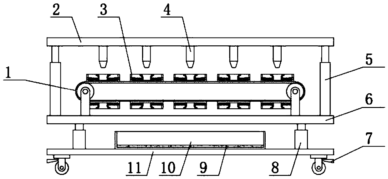
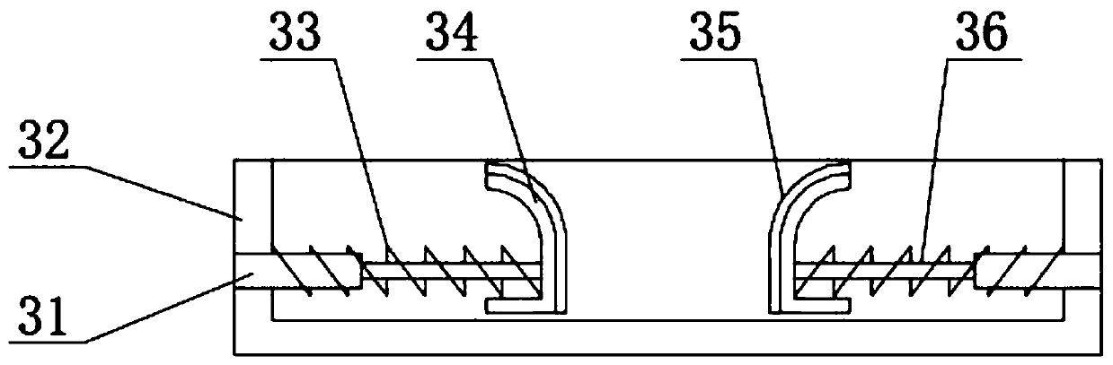
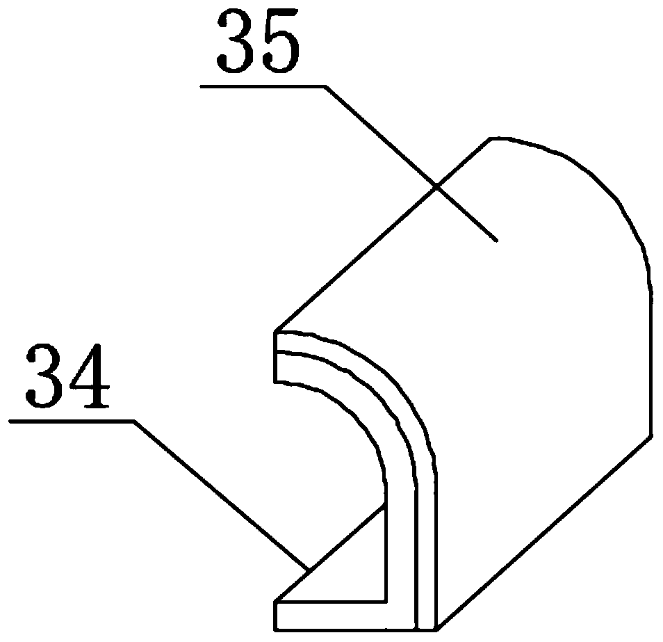
[0021] see Figure 1-Figure 4 , the present invention provides a technical solution: a conveyor rack for cosmetic box filling, including a second support plate 6, a first support plate 2 is arranged above the second support plate 6, and the upper surface of the second support plate 6 is two The end is welded with the first electric telescopic rod 5 corresponding to the first support plate 2, the lower surface of the first support plate 2 is provided with a feeding nozzle 4, and the conveyor belt 1 is provided under the feeding nozzle 4, and the surface of the conveyor belt 1 is provided with Fixed mechanism 3 is arranged, and fixed mechanism 3 comprises limit base 32, and the inside of limit base 32 is provided with fixture 34, and the bottom end of fixture 34 is provided with limit bar 36, and the bottom end of limit base 32 is provided with limiter. The limit tube 31 corresponding to the rod 36, the limit spring 33 is arranged on one side of the fixing member 34, and the ant...

Embodiment 2

[0025] see Figure 1-Figure 4 , on the basis of embodiment 1, the cosmetic box filling conveyor frame of embodiment 2 includes a second support plate 6, the top of the second support plate 6 is provided with a first support plate 2, and the upper surface of the second support plate 6 The two ends are welded with the first electric telescopic rod 5 corresponding to the first support plate 2, the lower surface of the first support plate 2 is provided with a feeding nozzle 4, and the lower surface of the feeding nozzle 4 is provided with a conveyor belt 1, and the surface of the conveyor belt 1 Fixed mechanism 3 is provided, and fixed mechanism 3 comprises limit base 32, and the inside of limit base 32 is provided with fixture 34, and the bottom end of fixture 34 is provided with limit bar 36, and the bottom end of limit base 32 is provided with and limit. The position-limiting tube 31 corresponding to the position bar 36 is provided with a position-limiting spring 33 on one side...


PUM


Abstract

The invention discloses a conveying frame for cosmetic box filling, and belongs to the technical field of cosmetic processing equipment. The conveying frame comprises a second supporting plate, wherein a first supporting plate is arranged above the second supporting plate; first electric telescopic rods corresponding to the first supporting plate are arranged at the two ends of the upper surface of the second supporting plate; a feeding spray head is arranged on the lower surface of the first supporting plate; a conveying belt is arranged below the feeding spray head; a fixing mechanism is arranged on the surface of the conveying belt; the fixing mechanism comprises a limiting base; a fixing piece is arranged inside the limiting base; a limiting rod is arranged at the bottom end of the fixing piece; a limiting pipe corresponding to the limiting rod is arranged at the bottom end of the limiting base; and a limiting spring is arranged on one side of the fixing piece. The conveying frameis simple in structure and convenient to use, has a good fixing function, and can effectively prevent the position of a cosmetic box from deviating in the transportation process, so that normal filling of the cosmetic box by a user is guaranteed.

Description

technical field [0001] The invention belongs to the technical field of cosmetics processing equipment, and in particular relates to a conveying rack for cosmetic box filling. Background technique [0002] Chinese patent (publication No. CN205931452U) discloses a conveyor frame for cosmetic box filling, including a frame, horizontal rodless cylinders are fixed on the left and right sides of the top plate of the frame, and a connecting frame is fixed in the middle of the top plate of the frame. There are connecting blocks at the left and right ends of the plate, and the connecting blocks are fixedly connected to the moving block of the horizontal rodless cylinder by bolts. The cosmetic box fixing plate is fixed on the top surface of the conveying plate, and there are multiple installation through holes on the top plate of the connecting frame. The through hole corresponds up and down with the box body installation hole provided on the cosmetic box fixing plate, and the top sur...

Claims


Application Information

Patent Timeline
IPC IPC(8): B65B43/52B65B3/04
CPCB65B3/04B65B43/52
Inventor 谷勇段闰程吕维孝吴玲俐
Owner 湖南润丽生物科技有限公司
Why Eureka
Try Eureka