Hard plastic soil foundation existing high-speed railway embankment side width structure a construction method

A soil and foundation technology, applied in the direction of roads, buildings, tracks, etc., can solve problems such as difficult control, high-speed railway embankment width deformation, etc., to avoid the impact, reduce the impact, and reduce its own weight.

Pending Publication Date: 2020-02-21
CHINA RAILWAY ERYUAN ENG GRP CO LTD
View PDF0 Cites 4 Cited by
  • Summary
  • Abstract
  • Description
  • Claims
  • Application Information

AI Technical Summary

Problems solved by technology

[0004] The purpose of the present invention is to: aiming at the problems existing in the prior art, to provide a hard-plastic soil foundation existing high-speed railway embankment side

Method used


Image

  • Hard plastic soil foundation existing high-speed railway embankment side width structure a construction method

Examples


Embodiment 1

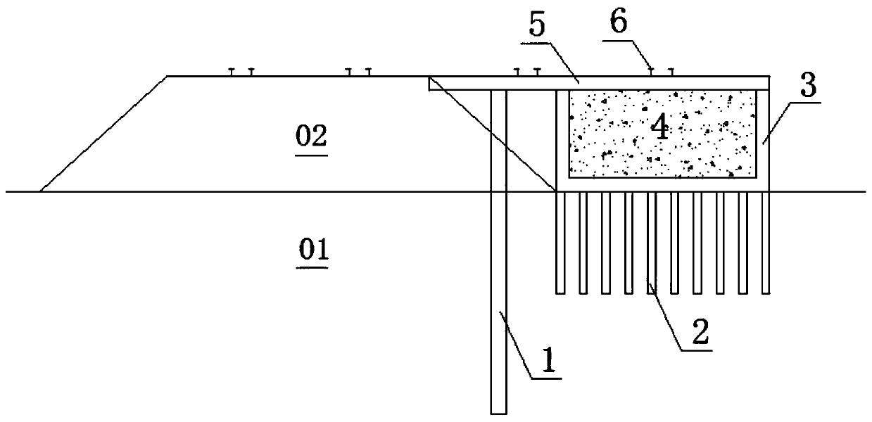
[0036] like figure 1 As shown, a kind of hard plastic soil foundation of the present invention has the wide structure of embankment side of high railway, including:

[0037] Several isolation support piles 1 are used to be arranged at intervals along the line on the slope of the existing filling body 02, and the bottom thereof goes deep into the hard plastic soil foundation 01; specifically, the diameter of the isolation support piles 1 is 1m-1.5m , the set spacing is 2m-4m;

[0038] Several CFG piles 2 are used to be arranged at intervals in the hard plastic soil foundation 01 outside the slope toe of the existing filling body 02; specifically, the depth of the isolation support pile 1 inserted into the hard plastic soil foundation 01 is greater than the The CFG pile 2 is inserted into the depth of the hard plastic soil foundation 01, and the setting depth of the CFG pile 2 is equal to or greater than the reinforcement depth of the existing high-speed rail foundation;

[00...

Embodiment 2

[0045] like figure 1 As shown, a kind of hard plastic soil foundation of the present invention has the construction method of the existing high-speed railway embankment width structure, which is used for construction as described in Example 1. The existing high-speed railway embankment width structure of the hard plastic soil foundation. The method includes the steps of:

[0046] A. On the existing filling body 02 slope, adopt a full casing drilling rig to drill and construct the isolation support pile 1, and reserve 30cm connecting steel bar at the pile top of the isolation support pile 1; the setting depth of the isolation support pile 1 meets According to the vertical deformation requirements of the side-width subgrade, the longitudinal spacing of the isolation support piles 1 along the line meets the stress transmission requirements of the side-width subgrade; specifically, the spacing is 2m-4m;

[0047] B. Construction of the CFG pile 2 in the hard plastic soil foundatio...


PUM

PropertyMeasurementUnit
Diameteraaaaaaaaaa

Abstract

The invention discloses a hard plastic soil foundation existing high-speed railway embankment side width structure and a construction method. The side width structure comprises a plurality of isolation supporting piles, a plurality of CFG piles, a groove-shaped structure, a light concrete body and a bearing plate, wherein the isolation supporting piles are used for being arranged on an existing fill side slope at intervals along a line, and the bottoms of the isolation supporting piles go deep into a hard plastic soil foundation; the CFG piles are used for being arranged in the hard plastic soil foundation on the outer side of the existing fill slope toe at intervals; the groove-shaped structure is used for being arranged on the hard plastic soil foundation on the outer side of the existing fill slope toe, an opening of the groove-shaped structure is arranged upwards, and all the CFG piles are connected to the bottom of the groove-shaped structure; the light concrete body is poured inside the groove-shaped structure, and the top surface of the light concrete body is flush with a groove opening of the groove-shaped structure; and the bearing plate is connected to the tops of the isolation supporting piles, the groove-shaped structure and the light concrete body, the top surface of the bearing plate is flush with the top surface of an existing fill, and one end of the bearing plate is placed on an existing fill road shoulder structure. According to the side width structure, the influence on the existing high-speed railway fill is effectively avoided.

Description

technical field [0001] The invention relates to the field of high-speed railway engineering, in particular to a hard-plastic soil foundation existing high-speed railway embankment width structure and a construction method. Background technique [0002] High-speed railways are developing rapidly in my country. At present, my country's large high-speed railway network has been basically completed. However, with the increasing local demand, the construction of high-speed railway branch networks is increasing. In the construction of high-speed railway branch networks, many new high-speed Railways need to run parallel to existing high-speed railways, or even need to be built adjacent to existing high-speed railways or need to widen existing high-speed railways. [0003] High-speed railways have strict requirements on deformation. Ballastless track high-speed railways are controlled at the millimeter level. Adding loads near existing high-speed railways will undoubtedly cause unfav...

Claims


Application Information

Patent Timeline
IPC IPC(8): E01B2/00
CPCE01B2/00
Inventor 姚裕春吴沛沛刘彬李宁张耀袁碧玉
Owner CHINA RAILWAY ERYUAN ENG GRP CO LTD
Why Eureka
Try Eureka