Supercharge Your Innovation With Domain-Expert AI Agents!

Shearing system for longwall mining

一种长壁、剪切机的技术,应用在剪切系统领域,能够解决错误、不正确布置等问题

Pending Publication Date: 2020-02-21
CATERPILLAR INC
View PDF18 Cites 0 Cited by
  • Summary
  • Abstract
  • Description
  • Claims
  • Application Information

AI Technical Summary

Problems solved by technology

However, the extrapolated profile of the end of the chute bank may misrepresent the actual profile of the end of the chute bank, often resulting in the Incorrect arrangement at part)

Method used


Image

  • Shearing system for longwall mining
  • Shearing system for longwall mining
  • Shearing system for longwall mining

Examples


Embodiment Construction

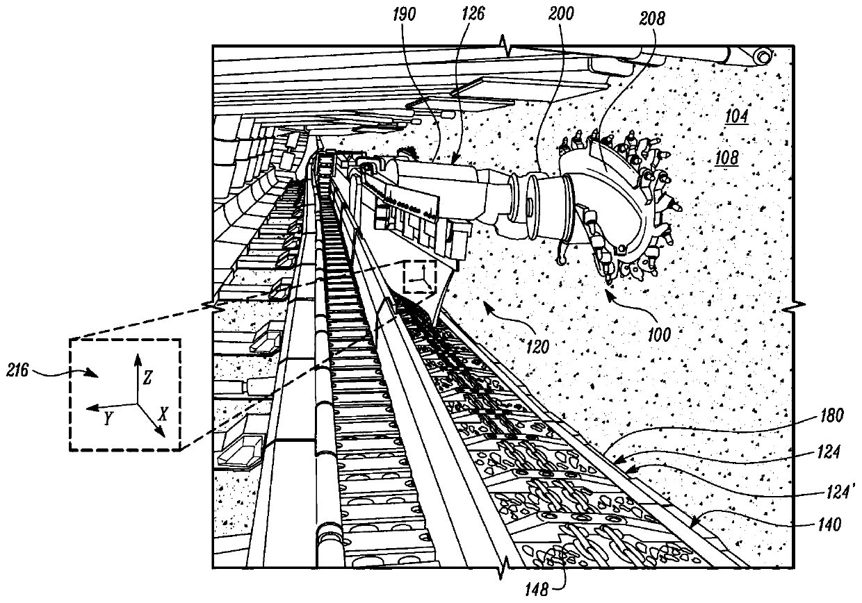
[0010] refer to figure 1 , a longwall mining machine 100 is shown. The longwall mining machine 100 may operate within an underground mine 104 to remove mineral material, such as coal, from a mining face 108 of the underground mine 104 . However, aspects of the invention may be applied to other environments, and may not be limited to those set forth in the following description and / or drawings. The longwall mining machine 100 may include a shearing system 120 having a face conveyor 124, a shearing machine 126, and a control system 128 (see figure 2 ).

[0011] see figure 1 and 2 , the face conveyor 124 may be an armored face conveyor 124 ′ and may be arranged and extended along the mining face 108 of the underground mine 104 . For example, face conveyor 124 may be located between main gate 130 and tail gate 132 of underground mine 104 (see figure 2 Exemplary notes in ) are extended between. Face conveyor 124 may include a plurality of face conveyor segments, referred t...


PUM


Abstract

A shearing system for longwall mining includes a pan line having an end stop, a gate end, and a set of consecutively arranged pans 160 extending from the gate end and having one or more pans disposedbeyond the end stop. A shearer is stoppable at the end stop, includes a shearer arm and is positioned on the one or more pans when the shearer arm is disposed between the end stop and the gate end. Afirst sensor detects an orientation of the shearer, while second sensors detect an orientation of the set of consecutively arranged pans. A control system determines a profile of the pan line betweenthe end stop and the gate end and controls a movement of the shearer arm based on the profile of the pan line when the shearer arm is disposed between the end stop and the gate end.

Description

technical field [0001] The present invention relates generally to shear systems for use in longwall mining. More specifically, the present invention relates to determining the profile of groups of chutes in a chute bank of a longwall mining machine by using sensors (eg, inclinometers). Background technique [0002] Longwall mining operations typically employ shears that move back and forth along armored face trough banks (or simply trough banks) to shear and extract material from the mining face. For example, shears include shear arms that can be used to shear material from a mining face. Shears typically include sensors, such as an inertial navigation system (INS), that facilitate measuring the orientation of the shear and thus the profile of the chute bank. Due to the shearer's generally elongated profile, the shearer typically cannot travel all the way to the end of the chute bank (or the main and tailgate ends of the chute bank). As a result, the profile of the end of...

Claims


Application Information

Patent Timeline
Patent Type & Authority Applications(China)
IPC IPC(8): E21C29/00E21F13/00E21C25/06
CPCE21C29/00E21F13/006E21C25/06E21C35/06E21C35/24E21C25/56E21C25/00E21C35/00E21C25/16E21C25/68E21C27/32E21C35/12E21C41/16
Inventor E·R·柯克霍普
Owner CATERPILLAR INC
Features
  • R&D
  • Intellectual Property
  • Life Sciences
  • Materials
  • Tech Scout
  • Unparalleled Data Quality
  • Higher Quality Content
  • 60% Fewer Hallucinations
Learn More