Precise composite suction and exhaust valve

A precision technology for intake and exhaust valves, applied in valve details, valve devices, valve operation/release devices, etc., can solve problems affecting normal life, exhaust pipe rust, failure, etc., so that it is not easy to block and fail , thorough exhaust and reasonable structure

Pending Publication Date: 2020-02-21
奎屯耐特阀门科技有限公司
View PDF2 Cites 1 Cited by
  • Summary
  • Abstract
  • Description
  • Claims
  • Application Information

AI Technical Summary

Problems solved by technology

[0002] There is often air inside facilities such as water pipelines or containers. Under the joint action of water flow and air flow, pipe bursts often occur. In addition, many water pipelines use PVC pipes. When the water is too large, due to the Under the action of negative pressure, it is easy to flatten the pipeline, deform or break it, and these are prone to large-scale water outages, which not only affect people's normal life, but also consume a lot of manpower and material resources for emergency repairs, which are normal. The water supply has brought a big problem. The Chinese invention patent application publication number CN104613207A discloses a "pipe exhaust valve". The valve body is installed at the end of the drain pipe body. There is a water inlet and a drain connected to the end of the drain pipe body. The pipeline exhaust valve includes a gas collection device inside the valve body and a buoy exhaust device. The gas collection device is arranged at the lower part of the valve body, and the buoy The exhaust device is located on the upper part of the gas collection device. Although this pipeline exhaust valve can be designed to collect and exhaust gas as a whole, and there is a gas collection ring inside the valve to concentrate and discharge the air bubbles in the water flow through the valve, but this kind of The exhaust valve adopts the principle of a float and a lever, which is prone to failure. In addition, when the air flow in the pipe is too large, it is easy to directly blow up the float, thereby blocking the exhaust port. Due to the large internal and external pressure difference, If the exhaust port cannot be opened, the function of exhaust will not be achieved, and the reliability is relatively poor. A Chinese utility model patent with the authorized announcement number CN206093156 discloses a "pipeline automatic intake and exhaust valve", which is installed in the valve body Floating ball outer barrel, a floating ball is set in the floating ball outer barrel, the top of the floating ball is provided with a floating ball gland and a guide exhaust pipe, and a number of guide exhaust pipe holes are arranged on the guide exhaust pipe from top to bottom , in the middle of the spool at the top of the bonnet, there is a guide pipe for connecting the exhaust pipe, on the spool around the guide pipe, there is an exhaust inner pipe, and on the side wall at the top of the spool, there is a connecting exhaust inner pipe When the gas in the pipe is too much, it can be quickly released through the fence hole of the outer barrel of the floating ball, and when the gas in the pipe is less, it can also be discharged from time to time through the secondary exhaust hole in the middle of the elastic sleeve. It can also quickly inhale air when the pipeline generates negative pressure to prevent deformation and rupture of the water delivery pipeline, and the reliability is also stronger. However, the shortcomings of the automatic intake and exhaust valve of this pipeline are as follows:
[0003] One is that the floating ball gland at the top of the floating ball is separated. After a period of use, the guiding and exhaust pipes are easily rusted by scale and cause failure, especially in the case of small intake and exhaust volumes. The power of the engine is very small, and the probability of failure due to scale rust will increase
[0004] The second is that the floating ball has already sealed the secondary exhaust hole on the elastic sleeve at the initial stage of the floating ball. In fact, the secondary exhaust hole on the elastic sleeve did not play the role of micro-exhaust.

Method used


Image

  • Precise composite suction and exhaust valve
  • Precise composite suction and exhaust valve
  • Precise composite suction and exhaust valve

Examples


Embodiment 1

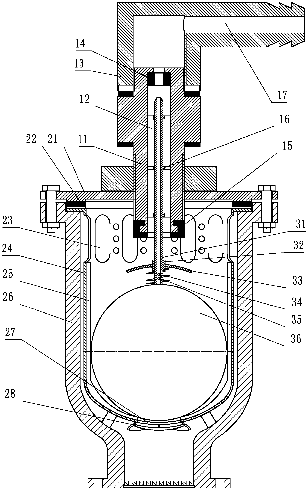
[0025] Embodiment 1: refer to Figure 1-2 , is a structural schematic diagram of Embodiment 1 of the present invention, including a valve body 26, a valve cover 21, a valve column 11, a float closure 15, a valve column end cover 13, a float outer barrel 24, a float outer barrel fence hole 23, a guide Exhaust pipe 31, ball float gland 33, and ball float 36, described spool 11 is connected on the bonnet 21 by thread, the end of spool 11 extends downwards to the middle part of float outer bucket 24, and spool 11 is provided with a positioning piece, which is connected to the outside of the spool 11 through threads, so as to control the depth of the end of the spool 11 extending into the float outer barrel 24 in the valve body 26. The float closure 15 is arranged on the valve The end of the spool 11 in the body 26, the spool end cover 13 is a connector provided with a card interface, which can be connected to a hose.

[0026] The middle of the spool 11 is provided with a first ex...

Embodiment 2

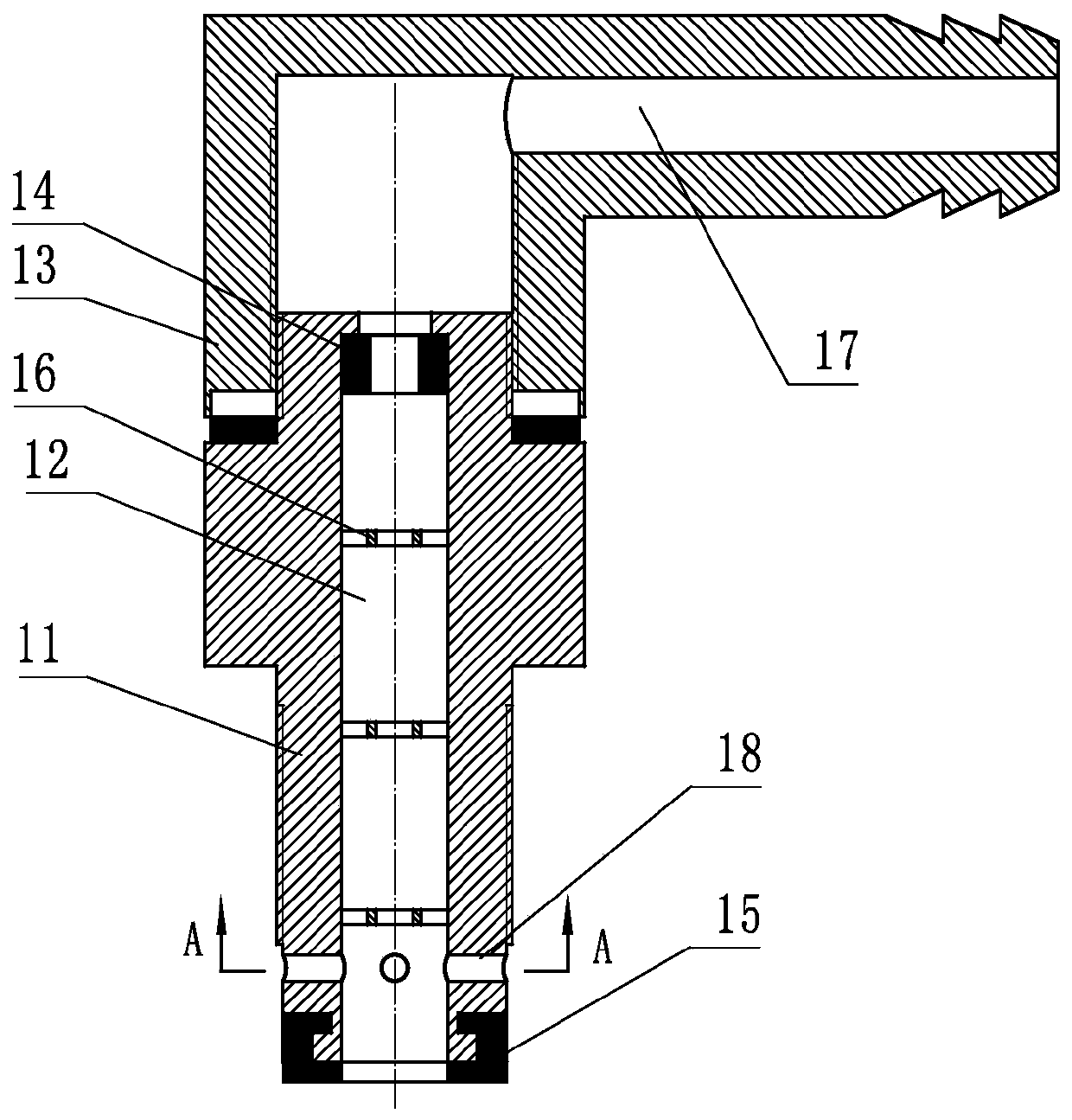
[0029] Embodiment 2: refer to Figure 3-4 , is a schematic structural view of Embodiment 2 of the present invention. Compared with Embodiment 1, Embodiment 2 is different in that: the downward extension of the valve column 11 is provided with a transverse air hole 18 .

Embodiment 3

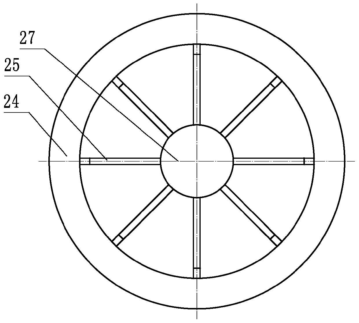
[0030] Embodiment 3: refer to Figure 5 , is a structural schematic diagram of Embodiment 3 of the present invention. Compared with Embodiment 1, Embodiment 2 is different in that: the convex rib 25 is the bending of the body of the float outer barrel 24, which is described in this embodiment. The plate corrugated strips are provided with 3 on the inwall of the float outer bucket 24.


PUM


Abstract

The invention discloses a precise composite suction and exhaust valve. The precise composite suction and exhaust valve comprises a valve body (26), a valve cover (21), a valve column (11), a float sealing piece (15), a valve column end cover (13), a floating ball outer barrel (24), a guide exhaust pipe (31), a floating ball gland (33) and a floating ball (36), wherein a first exhaust hole (12) anda guide mechanism (16) are arranged in the middle of the valve column (11); the guide exhaust pipe (31) is fixedly arranged on the floating ball (36); the floating ball gland (33) is connected to theguide exhaust pipe (31) through a sliding sleeve (32); and a return spring (34) is arranged between the floating ball gland (33) and the floating ball (36). Compared with the prior art, a split structure is adopted for the precise composite suction and exhaust valve, the precise composite suction and exhaust valve is more reasonable in structure, is not prone to blockage failure, can perform micro-exhaust through a secondary exhaust hole after a large amount of exhaust is finished, is more thorough in exhaust, is particularly suitable for occasions requiring precise exhaust, and can effectively guarantee the safety of facilities such as water delivery pipelines or containers.

Description

technical field [0001] The invention relates to an exhaust valve device, in particular to a precision composite intake and exhaust valve. Background technique [0002] There is often air inside facilities such as water pipelines or containers. Under the joint action of water flow and air flow, pipe bursts often occur. In addition, many water pipelines use PVC pipes. When the water is too large, due to the Under the action of negative pressure, it is easy to flatten the pipeline, deform or break it, and these are prone to large-scale water outages, which not only affect people's normal life, but also consume a lot of manpower and material resources for emergency repairs, which are normal. The water supply has brought a big problem. The Chinese invention patent application publication number CN104613207A discloses a "pipe exhaust valve". The valve body is installed at the end of the drain pipe body. There is a water inlet and a drain connected to the end of the drain pipe bod...

Claims


Application Information

Patent Timeline
Patent Type & Authority Applications(China)
IPC IPC(8): F16K31/18F16L55/07
CPCF16K31/18F16L55/07
Inventor 隋春升
Owner 奎屯耐特阀门科技有限公司
Why Eureka
Try Eureka