Cooking utensil
A technology for cooking utensils and bodies, which is applied in the field of microwave ovens, can solve the problems of accumulation of water and food residues, poor heating uniformity, and difficulty in cleaning, and achieves the effects of simplifying the structure, reducing assembly procedures, and facilitating cleaning.
- Summary
- Abstract
- Description
- Claims
- Application Information
AI Technical Summary
Problems solved by technology
Method used
Image

Examples
Embodiment 1
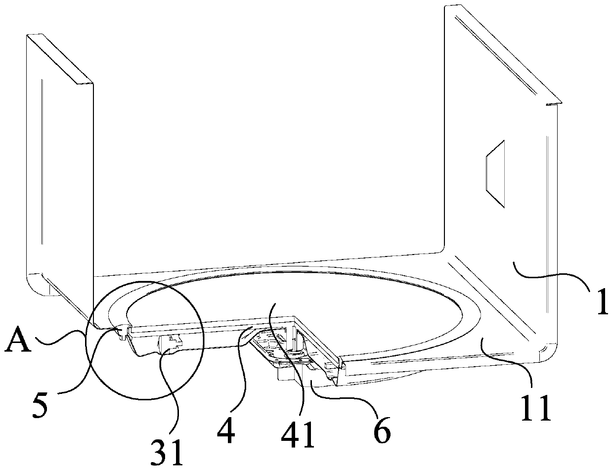
[0085] Such as figure 1 and figure 2 Shown, one embodiment of the present invention proposes a kind of cooking appliance, defines:
[0086] The cooking utensil includes a cavity bottom plate 11 and a turntable body 4. A downwardly recessed recess 12 is provided on the cavity bottom plate 11. The turntable body 4 is arranged in the recess 12, and the upper surface of the loading portion 41 of the turntable body 4 It is flat with the upper surface of the cavity bottom plate 11, so that the transition between the turntable body 4 and the cavity bottom plate 11 is smooth, so as to facilitate cleaning. Among them, a plurality of rolling elements 31 are also arranged in the recessed part 12, and the plurality of rolling elements 31 support the turntable body 4, to realize the rotation and / or support of the turntable body 4.
[0087] Optionally, a plurality of rolling bodies 31 are in contact with the turntable body 4, and when the rolling bodies 31 are rolling, the rolling bodies...
Embodiment 2
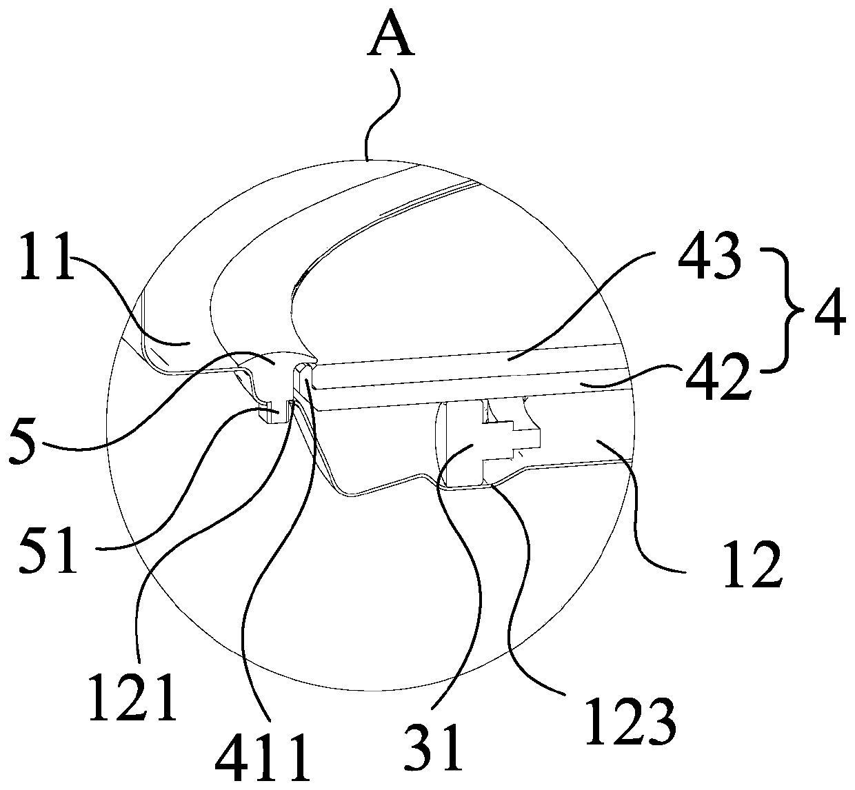
[0092] Such as figure 2 Shown, on the basis of embodiment 1, further define:
[0093] A seal 5 is also provided between the turntable body 4 and the cavity bottom plate 11. The seal 5 is ring-shaped, and the outer wall of the seal 5 is against the cavity bottom plate 11, so that the cavity bottom plate 11 is closely attached to the inner wall of the seal 5. and the inner wall of the sealing member 5 is set correspondingly to the edge of the turntable body 4, so that the gap between the edge of the turntable body 4 and the cavity bottom plate 11 is sealed by the sealing member 5, so as to avoid the entry of water, food residues, etc., to facilitate Cavity bottom plate 11 and turntable body 4 are cleaned.
Embodiment 3
[0095] Such as Figure 4 Shown, on the basis of embodiment 2, further define:
[0096] One end of the loading portion 41 of the turntable body 4 that extends radially outward is bent upward to form a guide portion 411 , so that the upwardly bent end of the guide portion 411 is close to the bottom plate 11 of the cavity, so as to pass through the guide portion 411 and the seal 5 . The corresponding setting of the inner wall improves the sealing effect.
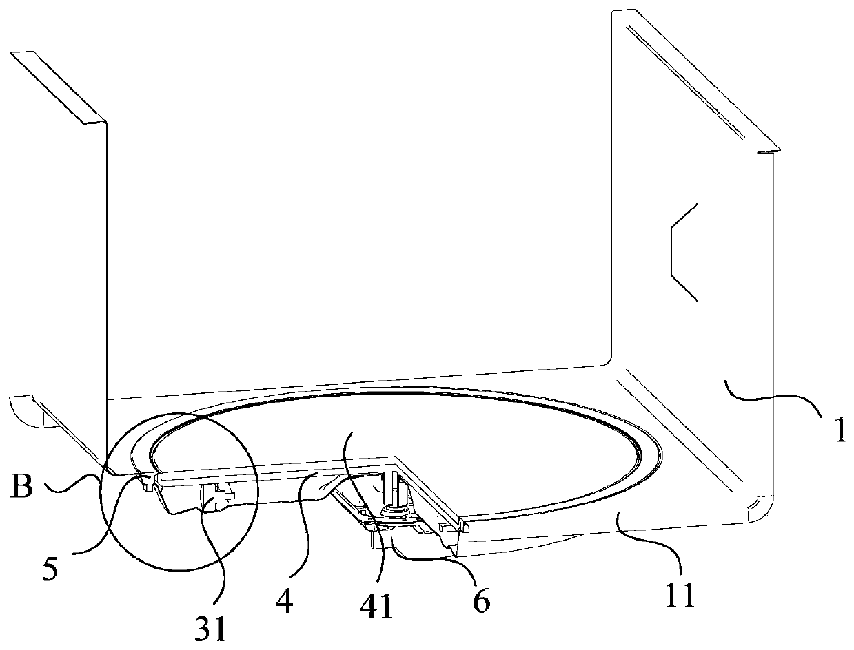
[0097] Such as Figure 6 As shown, optionally, one end of the turntable body 4 extending radially outward is bent downward to form a guide portion 411, and the side of the guide portion 411 close to the seal 5 is provided with an annular inclined surface, and the inner wall of the seal 5 is in contact with the The annular inclined surface of the guide part 411 is correspondingly provided with an annular inclined surface, so that an annular gap is formed between the sealing member 5 and the guide part 411 to realize gap sealin...
PUM
 Abstract
Description
Claims
Application Information
 - R&D
- Intellectual Property
- Life Sciences
- Materials
- Tech Scout
- Unparalleled Data Quality
- Higher Quality Content
- 60% Fewer Hallucinations
Browse by: Latest US Patents, China's latest patents, Technical Efficacy Thesaurus, Application Domain, Technology Topic, Popular Technical Reports.
© 2025 PatSnap. All rights reserved.Legal|Privacy policy|Modern Slavery Act Transparency Statement|Sitemap|About US| Contact US: help@patsnap.com