18F digital conforming monitoring device and monitoring method

A monitoring device and 18F technology, applied in the field of radioactive leakage monitoring in nuclear power plants, can solve the problem of inability to accurately monitor the leakage rate of coolant water at the pressure boundary of the primary circuit, and achieve the effect of improving detection efficiency

Pending Publication Date: 2020-02-21
NANHUA UNIV
View PDF6 Cites 7 Cited by
  • Summary
  • Abstract
  • Description
  • Claims
  • Application Information

AI Technical Summary

Problems solved by technology

[0007] The purpose of the invention is to overcome the deficiencies of the prior art, and provide a 18 The F number conforms to the monitoring device and monitoring method, which is used to monitor the nuclear power plant containment 18 F activity, eliminating monitoring inside the containment 18 Various interferences in the radioactivity of F have increased 18 F detection efficiency, which solves the problem that the existing technology cannot accurately monitor the leakage rate of coolant water at the pressure boundary of the primary circuit

Method used


Image

  • 18F digital conforming monitoring device and monitoring method
  • 18F digital conforming monitoring device and monitoring method
  • 18F digital conforming monitoring device and monitoring method

Examples


Embodiment 1

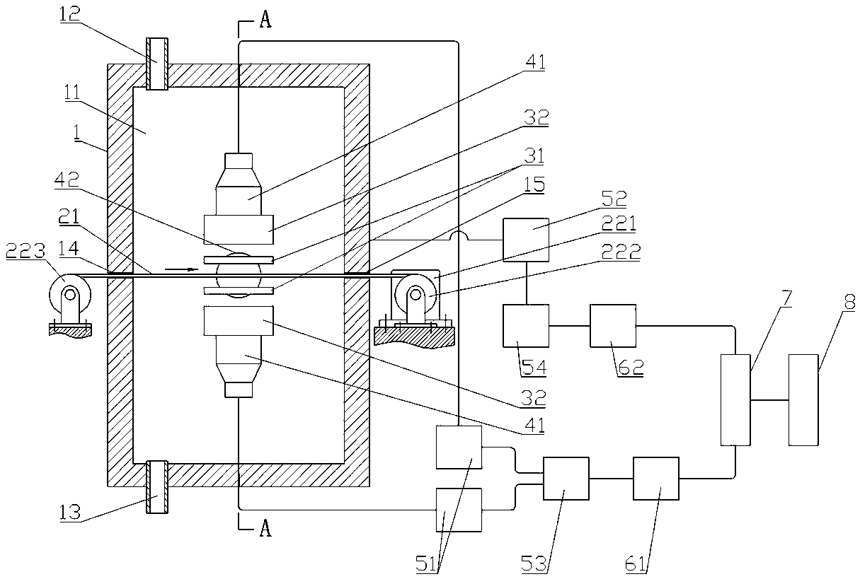
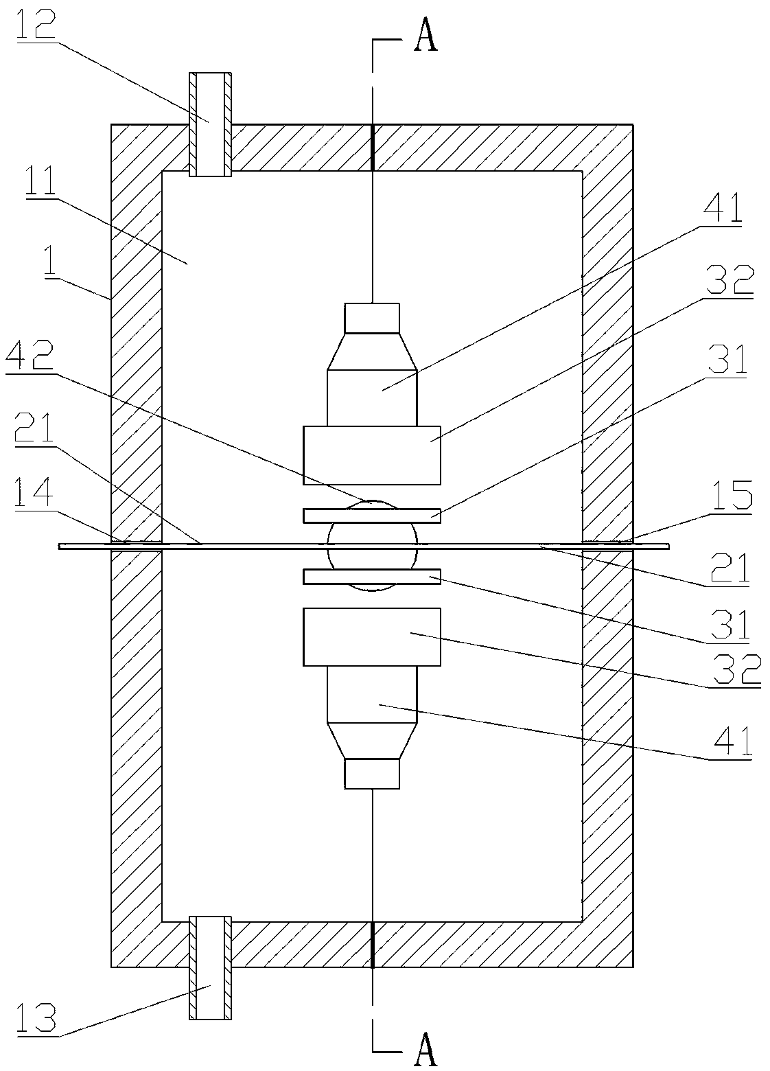
[0060] Such as Figure 1-4 as shown, 18 F digital coincidence monitoring device, including lead shielding shell 1, paper feeding mechanism, plastic scintillator detector 31, NaI detector 32, photomultiplier tube A41, photomultiplier tube B42, preamplifier A51, preamplifier B52, main amplifier A53, main amplifier B54, pulse discrimination shaping circuit A61, pulse discrimination shaping circuit B62, high-speed data acquisition card 7 and computer 8.

[0061] The lead shielding shell 1 is provided with a component installation cavity 11, and the lead shielding shell 1 is provided with an air inlet 12 and an air outlet 13 opposite to each other, and a paper inlet 14 and a paper outlet 15 opposite to each other. There are also threading holes.

[0062] The paper-feeding mechanism includes drive components and 18 F dust filter paper strip 21, one end of the filter paper strip 21 penetrates the component installation chamber 11 from the paper inlet 14, and the other end passes t...

Embodiment 2

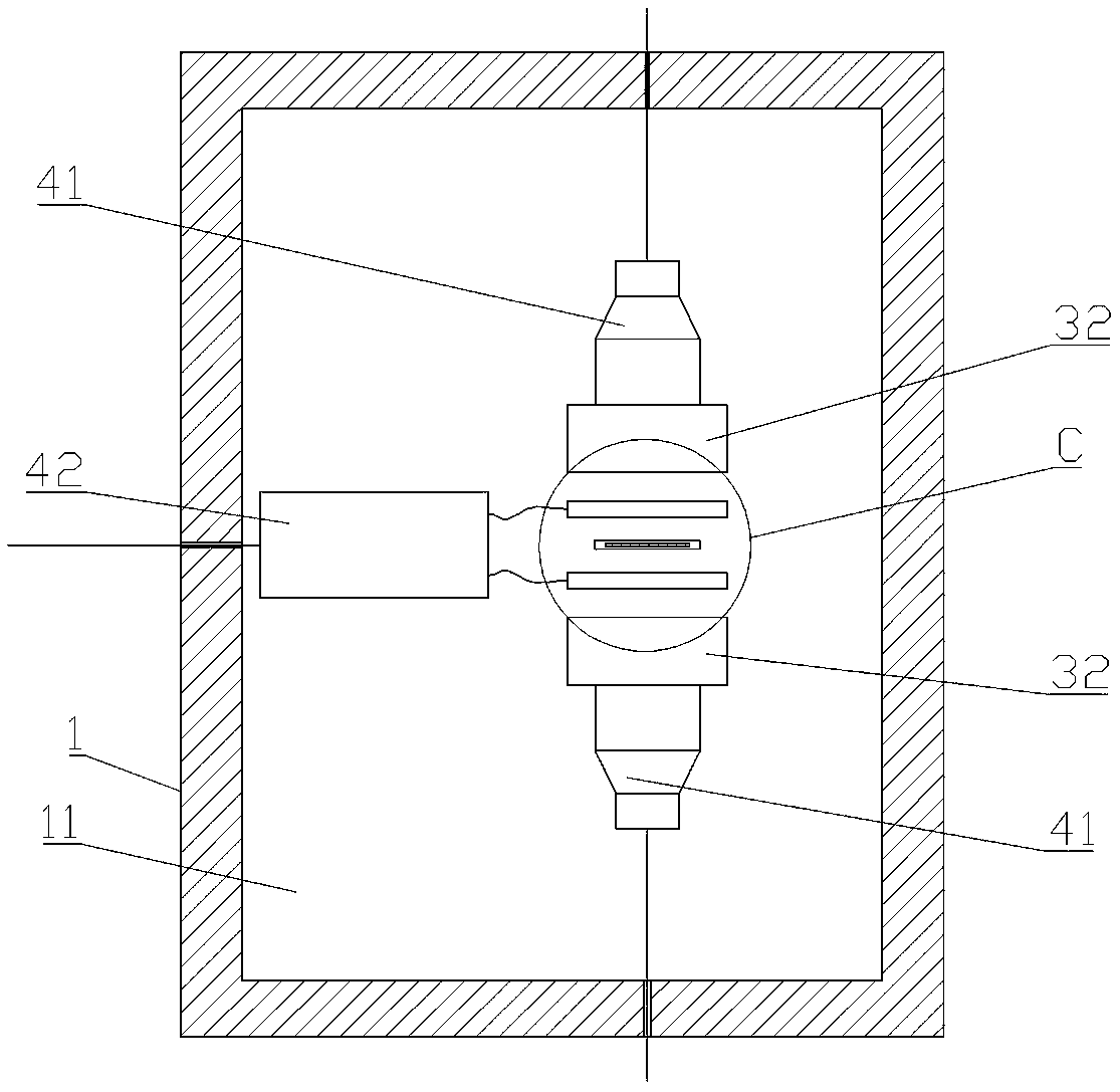
[0077] Such as Figure 5-8 As shown, the difference between this embodiment and Embodiment 1 is that in this embodiment, the number of plastic scintillator detectors 31 is one, and a through hole 311 for the filter paper strip to pass is provided on it, and it passes through The through hole 311 passes through the filter paper strip 21 , and its radiation receiving surface is the hole wall surface of the through hole 311 . A plastic scintillator detector 31 is located in the region between the two NaI detectors 32 .

[0078] Briefly describe the working process of the present invention:

[0079] one based on the above 18 The F number complies with the monitoring device's 18 F monitoring method, the steps are as follows:

[0080] S01, will 18 The F monitoring device is placed in the area to be monitored, and the air in the area is continuously entered into the component installation cavity 11 of the lead shielding shell 1 through the air inlet 12 through the external air p...


PUM


Abstract

The invention discloses a 18F digital conforming monitoring device and monitoring method, and relates to the technical field of radioactive leakage monitoring of a nuclear power plant. The 18F monitoring device comprises a lead shielding shell, a paper feeding mechanism, a plastic scintillator detector, a NaI detector, a photomultiplier A, a photomultiplier B, a pre-amplifier A, a pre-amplifier B,a main amplifier A, a main amplifier B, a pulse screening forming circuit A, a pulse screening forming circuit B, a high-speed data acquisition card and a computer. The 18F monitoring method is applied to the 18F digital conforming monitoring device. The 18F digital conforming monitoring device can be applied to the leakage monitoring of coolant water at the pressure boundary of the reactor primary circuit of the nuclear power plant, the radioactive activity of 18F mote in a reactor primary circuit containment can be measured on line, whether the reactor has the coolant water leakage or not is judged in real time, and the leakage rate of the coolant water is obtained by calculating.

Description

technical field [0001] The invention relates to the technical field of nuclear power plant radioactivity leakage monitoring, in particular to a 18 The F number conforms to the monitoring device and monitoring method. Background technique [0002] The pressure boundary of the primary circuit of the nuclear power plant reactor contains high temperature (+280℃~+320℃), high pressure (1.55Mpa), and coolant water with α, β, γ radioactivity, as well as the effects of mechanical wear and chemical corrosion, the primary circuit of the reactor Cracks and fissures can develop in the pressure boundary, allowing coolant water to leak. [0003] Once this kind of abnormal leakage occurs, the radioactive coolant water in the primary circuit will enter the containment vessel, causing air pollution in the containment vessel, and at the same time, it will cause a water loss accident in the reactor core, directly affecting the normal operation of the nuclear power plant and even the nuclear po...

Claims


Application Information

Patent Timeline
Patent Type & Authority Applications(China)
IPC IPC(8): G01T1/203G21C17/00G21C17/022
CPCG01T1/203G21C17/002G21C17/022Y02E30/30
Inventor 颜拥军谢宇希李翔
Owner NANHUA UNIV
Why Eureka
Try Eureka