A rotor intermediate ring structure and design method thereof

An intermediate ring and rotor technology, applied in the field of cage induction motor design, can solve problems such as differences in design methods, current characteristics of the intermediate ring, and heat dissipation conditions, and achieve uniform heat dissipation distribution, increased processing difficulty, and uniform heat dissipation

Active Publication Date: 2022-07-26
HEFEI UNIV OF TECH
View PDF0 Cites 0 Cited by
  • Summary
  • Abstract
  • Description
  • Claims
  • Application Information

AI Technical Summary

Problems solved by technology

However, because the intermediate ring is in a special position in the middle of the rotor winding, the current characteristics and heat dissipation conditions of the intermediate ring are different from those of the end ring, and the design method is different. At present, there is still a lack of research on the design method of the intermediate ring

Method used

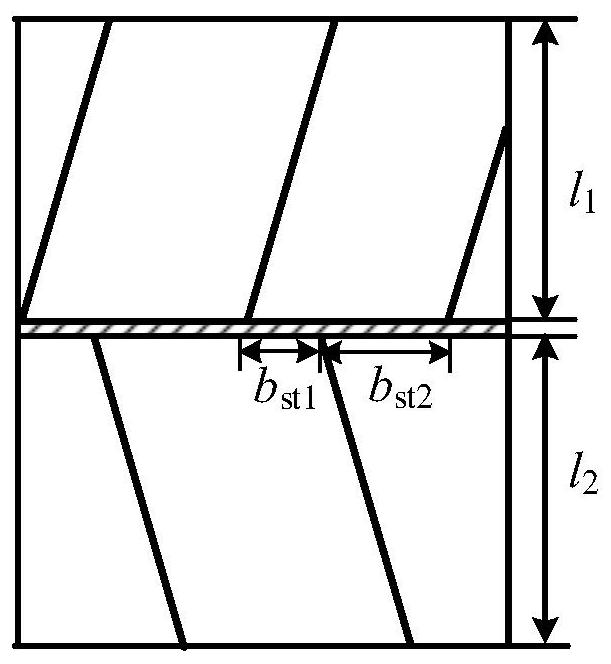
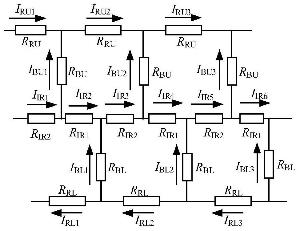
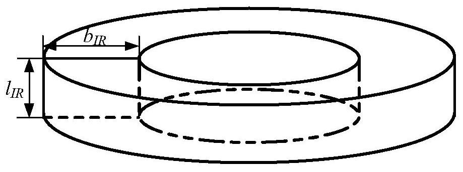

Image

  • A rotor intermediate ring structure and design method thereof
  • A rotor intermediate ring structure and design method thereof
  • A rotor intermediate ring structure and design method thereof

Examples


Embodiment Construction

[0042] The application will be described in further detail below in conjunction with the accompanying drawings. It is necessary to point out that the following specific embodiments are only used to further illustrate the application, and should not be construed as limiting the protection scope of the application. Those skilled in the art can The above application content makes some non-essential improvements and adjustments to this application.

[0043] like image 3 A rotor intermediate ring structure is shown, including an intermediate ring body, and the axial height of the intermediate ring body is: l IR ∈(0,l R / 3], where: l R is the axial height of the end ring. The radial width of the intermediate ring body is: b IR ∈[3b t2 / 4,(D2 -D 0 +6b t2 ) / 8], where: b t2 is the rotor slot height, D 2 is the outer diameter of the rotor, D 0 is the inner diameter of the rotor.

[0044] A method for designing a rotor intermediate ring structure, comprising the following ste...


PUM


Abstract

The invention discloses a rotor intermediate ring structure and a design method thereof. A rotor intermediate ring structure includes an intermediate ring body, and the axial height of the intermediate ring body is: l IR ∈(0,l R / 3], where: l R is the axial height of the end ring. The radial width of the intermediate ring body is: b IR ∈[3b t2 / 4,(D 2 ‑D 0 +6b t2 ) / 8]; a method for designing a rotor intermediate ring structure, comprising the following steps: determining that the electric density range of the intermediate ring is J IR =(J R ‑J B ); determine the relationship between the intermediate ring current amplitude and obtain the rotor equivalent resistance expression; estimate the intermediate ring current amplitude from the known bar current of the rotor motor without intermediate ring, and obtain the range of the intermediate ring cross-sectional area; choose Intermediate loop parameters at minimum equivalent resistance. On the basis of considering the actual processing situation of the rotor core, the invention ensures uniform heat dissipation of each part of the rotor winding of the intermediate ring, and minimizes the loss of the rotor winding.

Description

technical field [0001] The invention relates to the technical field of squirrel induction motor design, in particular to a rotor intermediate ring structure and a design method thereof. Background technique [0002] The traditional squirrel-cage rotor winding is composed of bar and end ring, and proper bar area and end ring area should be ensured when designing the motor structure. For the cage-cast aluminum rotors of ordinary small and medium-sized motors, the electrical density of the bars is usually B =(2.0-4.5)A / mm 2 , the end ring electrical density range J R =(0.45-0.8)J B . In order to ensure a large enough starting torque, the rotor resistance needs to be large enough, that is, the corresponding electric density cannot be too small; at the same time, if the rotor electric density is too large, the larger rotor resistance will increase the additional rotor winding loss and reduce the motor. Speed ​​at rated operation. If the rotor winding structure is not proper...

Claims


Application Information

Patent Timeline
Patent Type & Authority Patents(China)
IPC IPC(8): H02K17/16H02K15/00
CPCH02K17/165H02K15/0012H02K2213/03
Inventor 鲍晓华徐威许东滢汤亦追燕靖文朱然
Owner HEFEI UNIV OF TECH
Why Eureka
Try Eureka