

Information transmission method and device
A technology for information transmission and resource allocation information, applied in the field of information transmission methods and devices, can solve problems such as complex link switching process and prolongation of link interruption, so as to increase flexibility, avoid interruption delay, and solve link interruption time-prolonging effect
- Summary
- Abstract
- Description
- Claims
- Application Information
AI Technical Summary
Problems solved by technology
Method used
Image

Examples
Embodiment 1
[0031] An embodiment of the present application provides a mobile communication network (including but not limited to an IAB mobile communication network), and the network architecture of the network may include an IAB host entity part (also called a CU), a DU part, and a terminal. Wherein, the terminal includes a common terminal, and also includes a terminal function part of an IAB entity. This embodiment provides an information transmission method that can run on the above-mentioned network architecture. It should be noted that the operating environment of the above-mentioned information transmission method provided in the embodiment of the present application is not limited to the above-mentioned network architecture.
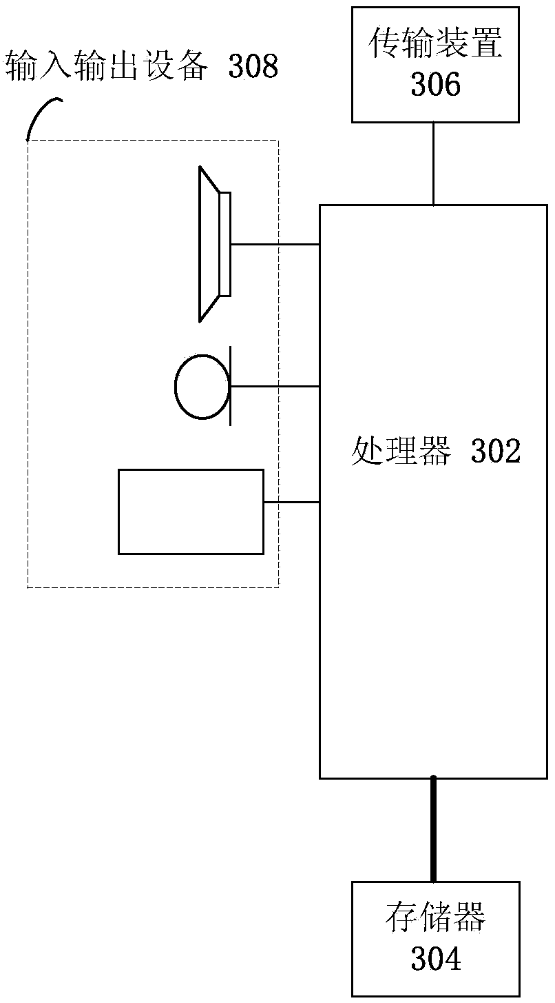
[0032] The method embodiment provided in Embodiment 1 of the present application may be executed in a mobile terminal, a computer terminal, or a similar computing device. Taking running on a mobile terminal as an example, image 3 It is a block diagram of a...
specific Embodiment 1
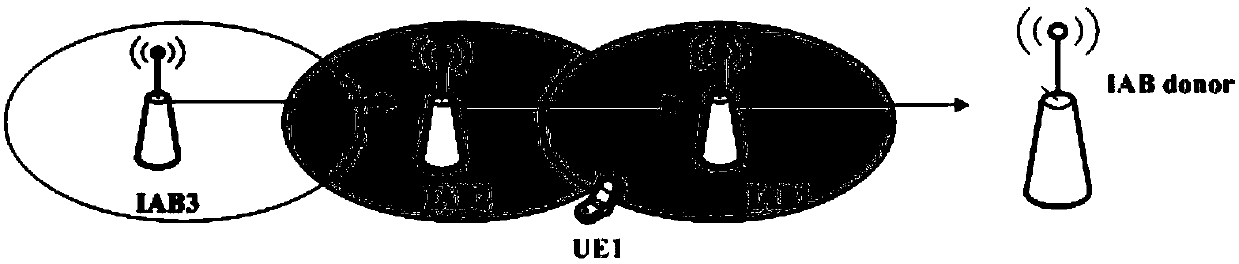
[0105] Figure 5 It is a schematic diagram of the specific embodiment 1 of the application document, such as Figure 5 As shown, in this embodiment, the UE is connected to M-DU1, and reports the measurement result to the donor CU, and the donor CU selects a secondary DU (S-DU) for the UE based on the measurement report.
[0106] Step 1. After selecting the S-Du based on the measurement report, the donor CU sends a UE Context Setup Request message to the S-DU for generating UE context information.
[0107] Wherein, the UE Context Setup Request message includes at least one of the following: an established but not activated cell group identifier; an established but not activated path identifier, including an uplink GTP tunnel identifier or a DU identifier; an established but not activated signaling bearer identifier; An established but not activated data bearer identity; an established detached bearer identity.
[0108] The RRCConnectionReconfiguration message includes at leas...
specific Embodiment 2
[0118] Image 6 It is a schematic diagram of the link conversion process according to the specific embodiment 2 of the present application, such as Image 6 shown, including the following steps:
[0119]Step 1: DU1 sends link failure or link congestion information to CU; wherein, link failure or link congestion information includes: link failure indication; link congestion indication; channel status report; link identification; DU identification; current load report.
[0120] Step 2: CU judges and decides to activate the link between DU2 and IAB;
[0121] Step 3: The donor-CU sends a UE context adjustment request message to DU2, including the RRCConnectionReconfiguration message generated for the UE;
[0122] Wherein, the UE Context Modification Request message includes at least one of the following: an activated signaling bearer identifier; an activated data bearer identifier; an activated path identifier, including an uplink GTP tunnel identifier or a DU identifier; an ac...
PUM
 Abstract
Description
Claims
Application Information