
LED lighting device

A technology for LED lighting and LED light groups, applied in electrical components and other directions, can solve problems such as difficulty in accurately finding LED chips, damage, etc.

Pending Publication Date: 2020-02-21
力普士科技(珠海)有限公司
View PDF0 Cites 1 Cited by
  • Summary
  • Abstract
  • Description
  • Claims
  • Application Information

AI Technical Summary

Problems solved by technology

[0004] However, a large number of LED chips and multiple LED lamp groups are usually integrated in the lighting device. Even if a certain LED lamp group is damaged and does not emit light, it is sometimes difficult to accurately find or judge which LED lamp group is the LED chip in. damage

Method used


Image

  • LED lighting device
  • LED lighting device
  • LED lighting device

Examples


no. 1 example

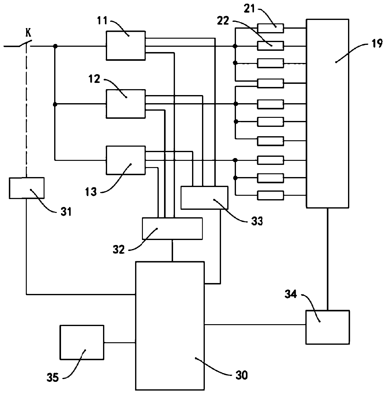
[0028] see figure 1 , the LED lighting device of this embodiment includes an AC switch K, one end of the AC switch K is connected to an AC power source, for example, receives 220V mains power, and the other end of the AC switch K is connected to a plurality of power modules, for example, connected to the power modules 11, 12, 13. Each power supply module 11, 12, 13 can receive AC power and convert the AC power into low-voltage DC power, and supply power to multiple groups of LED lights. Of course, each power supply module 11, 12, 13 can also filter and stabilize the converted DC power.

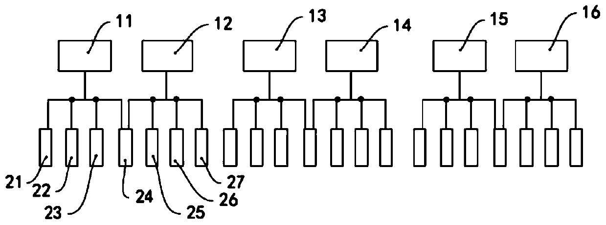
[0029] Each power module supplies power to at least two groups of LED lamp groups. Specifically, such as figure 2 As shown, the power module 11 supplies power to the LED lamp groups 21 , 22 , 23 , 24 , and multiple groups of LED lamp groups 21 , 22 , 23 , 24 connected to the same module 11 are connected in parallel. The power module 12 supplies power to the LED lamp groups 24 , 25 , 26 , 2...


PUM


Abstract

The invention relates to an LED lighting device which comprises a plurality of LED lamp sets. Each LED lamp set comprises a plurality of LED chips which are connected in series. The device further comprises a number of power supply modules. Each power supply module is used for supplying power to the at least two LED lamp sets. The device further comprises a fault detection circuit which comprisesgroups of current detection circuits and groups of voltage detection circuits. Groups of current detection circuits and groups of voltage detection circuits are arranged corresponding to a number of LED lamp sets. Each group of current detection circuit comprises a current detection resistor connected with the low-voltage end of one LED lamp set. Two input ends of a current amplifier are connectedwith two ends of a current detection resistor respectively. The current amplifier outputs an amplified current signal to a current comparison device. Each group of voltage detection circuit comprisesa voltage detection resistor connected with the high-voltage end of one LED lamp set, and one end of the voltage detection resistor is connected with a voltage comparison device. According to the invention, the specific position of a faulted LED lamp set can be detected and determined.

Description

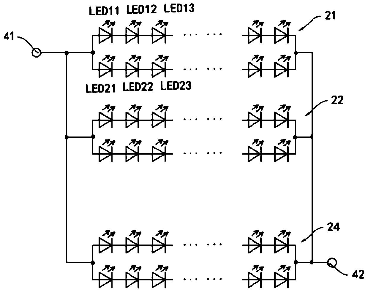
technical field [0001] The invention relates to the field of LED lighting; more specifically, it relates to an LED lighting device with a fault detection function. Background technique [0002] LEDs (Light Emitting Diodes) have the advantages of long service life and low power consumption, and have been widely used in various lighting devices. In some specific scenarios, people have high requirements for lighting brightness, so it is necessary to use high-power LED chips, or drive multiple LED chips to emit light at the same time. Usually, a plurality of LED chips are connected in series to form a group of LED lights. [0003] In order to meet lighting requirements, some lighting devices use multiple groups of LED lamps to provide sufficient lighting brightness / intensity. Usually, multiple groups of LED lamp groups are connected in parallel with each other, and the multiple groups of LED lamp groups are powered by the same power module, and the power module and the multipl...

Claims


Application Information

Patent Timeline
IPC IPC(8): H05B45/30
Inventor 李保忠杨美科梁建北
Owner 力普士科技(珠海)有限公司
Learn More