A synchronous removal of h in gas 2 s and so in the flue gas x with no x Methods

A gas and flue gas technology, applied in the field of gas and flue gas pollutant control, can solve problems such as difficulty in absorbing liquid regeneration, and achieve the effects of significant energy saving and environmental protection benefits, low operating costs, and simple operation.

Active Publication Date: 2022-02-18
TAIYUAN UNIV OF TECH
View PDF1 Cites 0 Cited by
  • Summary
  • Abstract
  • Description
  • Claims
  • Application Information

AI Technical Summary

Problems solved by technology

[0007] The present invention aims at technical problems such as the difficulty in regeneration of the absorption liquid in the existing wet desulfurization and denitrification integrated technology, and provides a method for synchronously removing H in gas. 2 S and SO in flue gas x with NO x The method can effectively solve the problem containing H 2 S, SO x with NO x Coking of other pollutants and other environmental problems of enterprises, with technical advantages such as less investment, simple operation, high treatment efficiency, and low operating costs

Method used


Image

  • A synchronous removal of h in gas  <sub>2</sub> s and so in the flue gas  <sub>x</sub> with no  <sub>x</sub> Methods

Examples


Embodiment 1

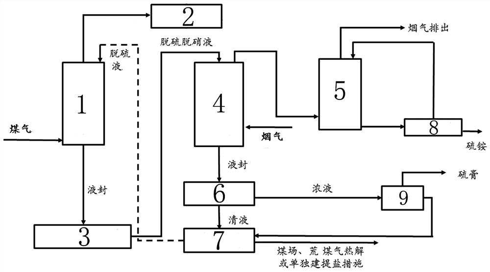
[0024] Embodiment 1: A kind of synchronous removal of H in gas 2 S and SO in flue gas x with NO x The method, described method is coal gas desulfurization and flue gas desulfurization denitrification process; Concrete steps are:

[0025] Coal gas desulfurization process: Coal gas A cooled to 35°C enters from the bottom of the gas desulfurization tower, and the H in gas A2 S concentration is 6g / m 3 , the desulfurization liquid uses ammonia as the alkali source, HPF as the desulfurization catalyst, the desulfurization liquid B is sprayed from the top of the gas desulfurization tower, the gas A and the desulfurization liquid B are in countercurrent contact and the H in the gas is removed 2 S, absorbing H through desulfurization liquid B 2 The gas A obtained after S is discharged from the top of the desulfurization tower, and the gas goes through the above process, and its H 2 S concentration reduced to 15mg / m 3 , the purified gas enters the follow-up ammonium sulfate system;...

Embodiment 2

[0027] Embodiment 2: A kind of synchronous removal of H in coal gas 2 S and SO in flue gas x with NO x The method, described method is coal gas desulfurization and flue gas desulfurization denitrification process; Concrete steps are:

[0028] Coal gas desulfurization process: H 2 S concentration is 10g / m 3 Coal gas A at a temperature of 40°C enters from the bottom of the gas desulfurization tower, and desulfurization liquid B is injected from the middle and upper part of the gas desulfurization tower. Desulfurization liquid B uses sodium carbonate as an alkali source and a complex iron desulfurization catalyst. B countercurrent contact and removal of H in the gas 2 S, absorbing H through desulfurization liquid B 2 The gas A obtained after S is discharged from the top of the desulfurization tower and enters the gas user. The H in the gas after desulfurization 2 S concentration is 12mg / m 3 ; absorb H 2 The desulfurized liquid B after S is discharged from the bottom of th...


PUM


Abstract

The invention belongs to the technical field of gas and flue gas pollutant treatment, and provides a method for synchronously removing H 2 S and SO in flue gas x with NO x The method, described method is gas desulfurization and flue gas desulfurization denitrification process; Make full use of the removal of H in gas 2 The desulfurization liquid after S carries out the SO in the flue gas x , NO x The removal of O in the flue gas while desulfurization and denitrification 2 Realize the regeneration of desulfurization liquid, and the solution after desulfurization and denitrification continues to return to the gas desulfurization tower for H in the gas 2 S removal. Coking and other enterprises H are realized with only one solution 2 S, SO x with NO x The integrated removal of wet desulfurization and denitrification effectively solves the technical problem of difficult regeneration of the absorption liquid in the integrated technology of wet desulfurization and denitrification. The whole process has the advantages of less investment, simple operation, high processing efficiency, and low operating costs. It is energy-saving and environmentally friendly. The benefits are remarkable.

Description

technical field [0001] The invention belongs to the technical field of gas and flue gas pollutant treatment, and more specifically, relates to a method for synchronously removing H from gas. 2 S and SO in flue gas x with NO x Methods. [0002] technical background [0003] Coke oven flue gas is the main source of exhaust gas pollution in coking enterprises, among which SO x and NO x It is an important cause of environmental problems such as acid rain, photochemical smog and smog. The "Coking Chemical Industry Pollutant Discharge Standard" issued in 2012 stipulates that after 2015, the coking oven NO x Emission concentration shall not exceed 500 mg / Nm 3 , SO 2 Emission concentration shall not exceed 50 mg / Nm 3 , for the geographical scope of special emission limits, NO x Emission concentration shall not exceed 150 mg / Nm 3 , SO 2 The concentration must be controlled at 30 mg / Nm 3 the following. If measures are not taken for existing and new coke ovens, the flue gas...

Claims


Application Information

Patent Timeline
Patent Type & Authority Patents(China)
IPC IPC(8): B01D53/60B01D53/78C10K1/00C10K1/12B01D53/52B01D53/86
CPCB01D53/78C10K1/004C10K1/121B01D53/60B01D53/8612Y02A50/20
Inventor 李国强王影张国杰段丽媛张舒婷刘俊张永发
Owner TAIYUAN UNIV OF TECH
Why Eureka
Try Eureka