Temperature bending deformation measurement of surface piezoelectric composite material

A piezoelectric composite material and curved surface technology, applied in measurement devices, analytical materials, thermal analysis of materials, etc., can solve the problem of affecting the frequency consistency of the transducer array primitives, reducing the water pressure resistance of the transducer, and reducing the beam of the transducer. Open angle change and other problems, to achieve the effect of solving the quantitative test problem of temperature deformation and improving environmental adaptability

Active Publication Date: 2020-02-25
中国人民解放军海军七0一工厂
View PDF7 Cites 1 Cited by
  • Summary
  • Abstract
  • Description
  • Claims
  • Application Information

AI Technical Summary

Problems solved by technology

Because the bending deformation of the piezoelectric composite material will have the following effects on the transducer and the sonar system: (1) frequency drift, affecting the frequency consistency of the transducer array elements, resulting in a decrease in the performance of the transducer array; The beam opening angle of the transducer changes, thereby reducing the positioning accuracy of the sonar system; (3) causing the piezoelectric composite material to peel off from the transducer backing, which reduces the water pressure resistance of the transducer; (4) severe deformation will cause The piezo composite fractured, resulting in complete destruction of the transducer

Method used


Image

  • Temperature bending deformation measurement of surface piezoelectric composite material
  • Temperature bending deformation measurement of surface piezoelectric composite material
  • Temperature bending deformation measurement of surface piezoelectric composite material

Examples


Embodiment Construction

[0052]In order to illustrate the present invention more clearly, the present invention will be further described below in conjunction with preferred embodiments and accompanying drawings. Similar parts in the figures are denoted by the same reference numerals. Those skilled in the art should understand that the content specifically described below is illustrative rather than restrictive, and should not limit the protection scope of the present invention.

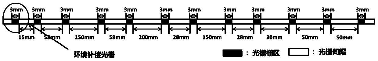
[0053] A fiber grating is a diffraction grating formed by periodically modulating the refractive index of the fiber core in the axial direction, and is a passive filter device. Because grating fiber has the advantages of small size and full compatibility with optical fiber, and its resonant wavelength is sensitive to changes in the external environment such as temperature and strain, it has been widely used in the field of sensing. The relationship between the wavelength change of the fiber grating reflected light and the s...


PUM

PropertyMeasurementUnit
lengthaaaaaaaaaa

Abstract

The invention provides temperature bending deformation measurement of a surface piezoelectric composite material. The temperature bending deformation measurement is implemented according to the stepsof providing a fiber formed with gratings; determining a measured position of a to-be-measured surface sample, and closely attaching each grating onto each surface of the to-be-measured sample by a pasting mode; measuring a length of a bonding region where the fiber at the measured position and the to-be-measured sample are pasted; changing an environmental temperature, monitoring a wavelength ofgrating reflection light under each temperature, and calculating strain of each fiber grating according to a relation between wavelength change quantity of the grating reflection light and the fiber grating to obtain measurement strain of each measured position; and obtaining an average strain value of the to-be-measured sample under each temperature according to the grating length of each measured position, the length of the bonding region and the corresponding measurement strain. By the method, a reliable basis is provided for detection of the piezoelectric composite material for a transducer, meanwhile, an effective check means is provided for improvement of a design and preparation process of the surface piezoelectric composite material, and the environmental adaptability of the transducer and a sonar system can be improved.

Description

technical field [0001] The invention belongs to the field of material deformation measurement, in particular to a method for measuring temperature bending deformation of curved piezoelectric composite materials. Background technique [0002] A transducer is a device for energy conversion, a device that converts one form of energy into another. Since sound waves are the only carrier that humans have mastered so far that can transmit information and energy over a long distance in the vast sea, most of the current underwater detection, communication, navigation, and mapping rely on underwater acoustic transducers. At present, the commonly used underwater acoustic transducers are mainly piezoelectric transducers, and the piezoelectric element (transducer element) is its core component, which directly determines the performance of the transducer. [0003] With the expansion of the application environment of the transducer, new requirements are put forward for the shape and vario...

Claims


Application Information

Patent Timeline
Patent Type & Authority Applications(China)
IPC IPC(8): G01B11/16G01N25/00
CPCG01B11/18G01N25/00
Inventor 王改丽申丽丽廖擎伟康冰琳李晋忠张晶晶肖文杰孙悦王丽坤桑作钧单晓艳
Owner 中国人民解放军海军七0一工厂
Why Eureka
Try Eureka