
Chamber liners, plasma reaction chambers and plasma equipment

A plasma and lining technology, applied in the field of plasma, can solve the problems of high speed of plasma extraction, low etching rate or deposition rate, etc., and achieve the effect of uniform reaction speed

Active Publication Date: 2022-07-22
BEIJING NAURA MICROELECTRONICS EQUIP CO LTD
View PDF8 Cites 0 Cited by
  • Summary
  • Abstract
  • Description
  • Claims
  • Application Information

AI Technical Summary

Problems solved by technology

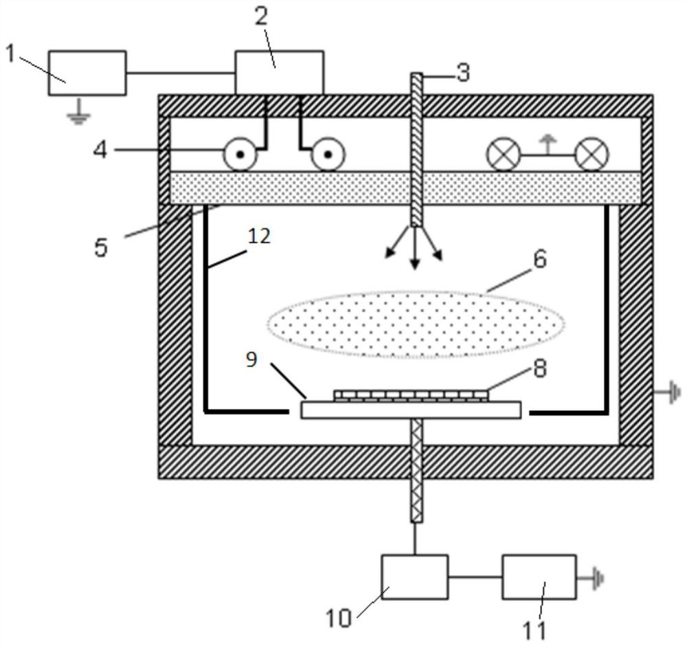
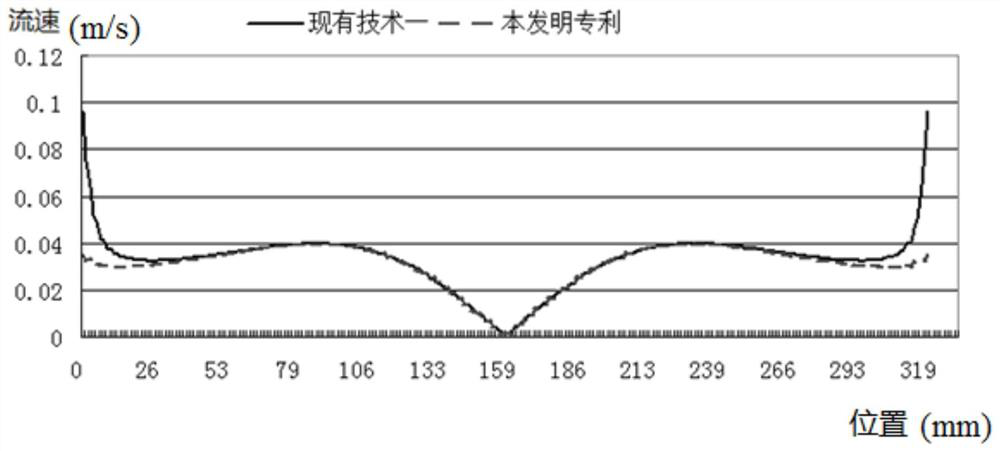
[0004] Existing plasma equipment exists that the plasma is extracted at the edge of the wafer 8 at an excessively high speed, resulting in the etching rate or deposition rate at the edge of the wafer being lower than the etching rate or deposition rate at the center of the wafer.

Method used


Image

  • Chamber liners, plasma reaction chambers and plasma equipment
  • Chamber liners, plasma reaction chambers and plasma equipment
  • Chamber liners, plasma reaction chambers and plasma equipment

Examples


Embodiment Construction

[0026] The specific embodiments of the present invention will be described in detail below with reference to the accompanying drawings. It should be understood that the specific embodiments described herein are only used to illustrate and explain the present invention, but not to limit the present invention.

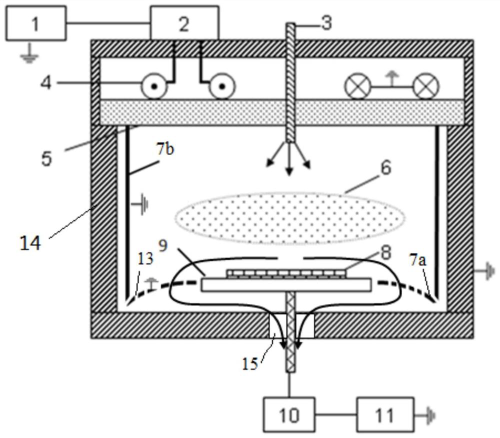
[0027] According to a first aspect of the present invention, a cavity inner liner is provided. As shown in 2, the cavity inner liner includes a bottom wall liner 7a and a side wall liner 7b, and the side wall liner 7b surrounds the bottom wall liner The body 7a is arranged to form a process chamber (that is, a space for accommodating the plasma 6), the middle of the bottom wall substrate 7a forms an accommodating opening for arranging the bias electrode 9, and the bottom wall substrate 7a is provided with a plurality of along the bottom wall The thickness direction of the lining body 7a runs through the air suction holes of the bottom wall lining body 7a. The upper surfa...


PUM


Abstract

The invention provides a cavity lining, a plasma reaction chamber and a plasma equipment. The cavity inner liner includes a bottom wall liner and a side wall liner, the side wall liner is arranged around the bottom wall liner to form a process cavity, and the middle of the bottom wall liner is formed for arranging a bias electrode The bottom wall liner is provided with a plurality of air extraction holes which penetrate through the bottom wall liner along the thickness direction of the bottom wall liner, and the upper surface of the bottom wall liner faces the process The cavity has a convex curved surface, and the height of the curved surface gradually decreases in the direction from the accommodating opening to the connection between the bottom wall liner and the side wall liner. The application of the cavity lining to the plasma equipment is beneficial to improve the consistency of the wafer surface reaction.

Description

technical field [0001] The present invention relates to the field of plasma technology, and more particularly, to a cavity lining, a plasma reaction chamber and a plasma equipment. Background technique [0002] Plasma equipment such as plasma etching equipment or plasma deposition equipment or the like. In plasma equipment, free radicals or ions in the plasma move to the wafer surface and interact with the wafer. The uniformity of the etching or deposition of the wafer is affected by the uniformity of the plasma distribution. The uniformity of plasma distribution is affected by the extraction of plasma and reaction by-products from the reaction chamber. [0003] see figure 1 The plasma device shown is a typical inductively coupled plasma device. The source RF source 1 delivers RF energy to the inductive coil 4 through the matcher 2 . The reaction gas enters the cavity through the gas inlet pipe 3 . The induction coil 4 excites the plasma 6 in the cavity space through t...

Claims


Application Information

Patent Timeline
Patent Type & Authority Patents(China)
IPC IPC(8): H01J37/32
CPCH01J37/32458H01J37/32431
Inventor 肖德志王建龙
Owner BEIJING NAURA MICROELECTRONICS EQUIP CO LTD
Learn More