Assisted joint training device and method

A training device and joint technology, applied in passive exercise equipment, physical therapy and other directions, can solve the problems of non-adjustable training intensity, secondary injury, increased patient pain, etc., and achieve the effect of complete functions, good applicability and convenient adjustment

Inactive Publication Date: 2020-02-28
HENAN INST OF SCI & TECH
8 Cites 2 Cited by

AI-Extracted Technical Summary

Problems solved by technology

Traditional rehabilitation training is performed by medical staff or family members during the treatment process, interspersed with compulsory activities of the elbow joint, that is, repeatedly stretching and flexing the arm with hands, forcing the elbow joint to move, so as to ensur...

Method used

Described forearm support 3 comprises two supporting arms 301 that are relatively arranged on the front and rear sides of described boom fixing seat 2, and one end of described supporting arm 301 is rotatably installed on the described boom fixing seat 2, The axis of rotation of the support arm 301 extends forward and backward; the inside of the two support arms 301 is provided with a slideway 5 extending along the length direction of the support arm 301, and a slideway 5 is installed between the two slideways 5. The forearm holder 4 is convenient to adjust the distance between the forearm holder 2 and the forearm holder 4 by sliding the forearm holder 4 according to the length of the user's arm; the outer side of the support arm 301 is fixedly installed with The auxiliary handle 302 is convenient to drive the forearm bracket 3 to rotate by pulling the auxiliary handle 302; the ends of the two support arms 301 away from the arm holder 2 are also fixedly installed with a connecting plate 303 to reinforce the two support ...

Abstract

The invention discloses an assisted joint training device and method thereof; an upper arm holder is fixedly mounted on a bottom plate, a forearm support is rotatably mounted on the upper arm holder,a forearm holder is movably mounted on the forearm support, a forearm holder locking mechanism is arranged between the forearm support and the forearm holder, a forearm holder traction mechanism is arranged on a base, and a forearm support rotation limiting mechanism is further arranged on the base; the forearm holder is locked on the forearm support, the forearm support is driven to rotate by pulling an assistant handle to perform passive movement training, or a hook is connected to a hanging ring by unlocking the forearm holder, a weight pulls the forearm holder leftwards through a tractionrope, the forearm holder pulls the forearm leftwards to perform joint tractive training, and the rotatable angle of the forearm support is gradually increased by continuously adjusting a retaining arm, so that the training intensity is gradually increased.

Application Domain

Technology Topic

Image

  • Assisted joint training device and method
  • Assisted joint training device and method
  • Assisted joint training device and method

Examples

  • Experimental program(1)

Example Embodiment

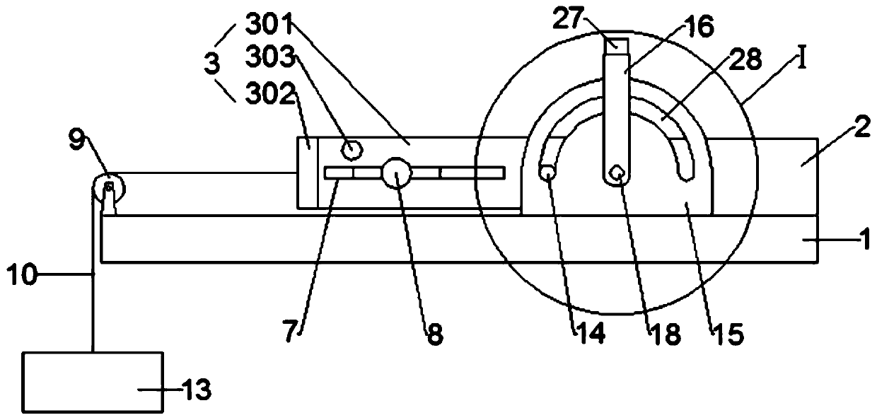
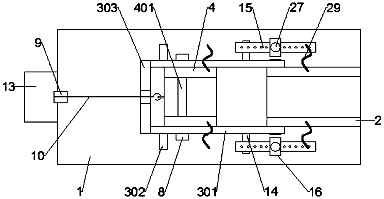
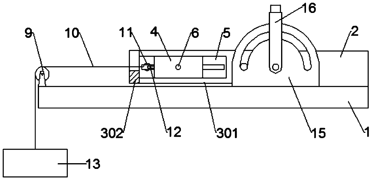
[0029] Such as Figure 1 to Figure 7 As shown, a joint auxiliary training device includes a bottom plate 1, on which a large arm fixing base 2 is fixedly installed, and a small arm bracket 3 is rotatably installed on the large arm fixing base 2, and the small arm bracket 3 A small arm fixing seat 4 is movably installed on the upper part. Both the big arm fixing seat 2 and the forearm fixing seat 3 are provided with arc grooves for placing arms, and the front and rear sides of the arc groove are provided with bindings. With 29, a hand grip 401 is fixedly installed in the arc-shaped groove of the forearm holder 4; a forearm holder locking mechanism is provided between the forearm support 3 and the forearm holder 4, so The base 1 is provided with a forearm fixing seat traction mechanism, and the base 1 is also provided with a forearm support rotation limit mechanism.
[0030] The forearm bracket 3 includes two support arms 301 arranged oppositely on the front and rear sides of the boom fixing seat 2. One end of the support arm 301 is rotatably mounted on the boom fixing seat 2. The axis of rotation of the arm 301 extends back and forth; the inner side of the two support arms 301 is provided with a slide 5 extending along the length of the support arm 301, and the small arm is slidably installed between the two slides 5 The fixing seat 4 is convenient for adjusting the distance between the big arm fixing seat 2 and the forearm fixing seat 4 by sliding the lower arm 4 fixing seat according to the length of the user's arm; an auxiliary handle 302 is fixedly installed on the outside of the supporting arm 301 , It is convenient to pull the auxiliary handle 302 to drive the forearm bracket 3 to rotate; the ends of the two support arms 301 away from the boom fixing seat 2 are also fixedly installed with a connecting plate 303 to strengthen the space between the two support arms 301 Connection.
[0031] Specifically, the forearm fixing seat locking mechanism includes threaded holes 6 located on the front and rear sides of the forearm fixing seat 4, and the outer side of the support arm 301 is provided with an elongated hole 7 communicating with the slideway 5 The length of the elongated hole 7 extends along the length of the support arm 301; it also includes a locking bolt 8, one end of the locking bolt 8 passes through the elongated hole 7 and is screwed in Inside the threaded hole 6. Lock the forearm fixing seat 4 on the forearm support 3 by tightening the tightening bolt 8 so that the forearm fixing seat 4 cannot move in the slideway 5; or loosening the tightening bolt 8 to unlock the forearm fixing seat 4, The forearm fixing seat 4 can move in the slideway 5.
[0032] In use, first adjust the position of the forearm fixing seat 4 according to the length of the user's arm, and adjust the distance between the forearm fixing seat 2 and the forearm fixing seat 4 by sliding the forearm 4 fixing seat. Tighten the locking bolt 8 to lock the forearm fixing seat 4 on the forearm support 3 so that the forearm fixing seat 4 cannot move in the slideway 5; then place the big arm of the injured arm in the forearm fixing seat 2 The forearm is placed in the forearm fixing seat 4 and fixed by a strap, and then the auxiliary handle 302 is pulled by the undamaged arm to drive the forearm support 3 to rotate, and the forearm support 3 drives the forearm fixing seat 4 Rotate, the forearm fixed seat 4 drives the forearm to rotate to bend the elbow joint for passive exercise training.
[0033] The traction mechanism includes a support wheel 9 fixedly mounted on the bottom plate 1, and the support wheel 9 is located on the left side of the arm support 3, and also includes a traction rope 10, one end of which is connected with a hook 11. The arm fixing seat 4 is provided with a hanging loop 12, the other end of the traction rope 10 extends downwards around the support wheel 9 and is connected with a load block 13, and the connecting plate 303 is provided with Trunking. When performing passive exercise training, it is necessary to remove the traction rope 10 from the forearm holder 4 to reduce the burden of rotating the forearm support 3; or loosen the tightening bolt 8 to unlock the forearm holder 4. The forearm fixing seat 4 can move in the slideway 5, the hook 11 is connected to the hanging ring 12, the 13 pieces of weight are pulled to the left by the traction rope 10, and the forearm fixing seat 4 pulls the forearm to the left. Perform joint traction training.
[0034] The arm support rotation limit mechanism includes a protrusion 14 fixedly mounted on the outer side of the support arm 301, and an auxiliary plate 15 located on the outer side of the support arm 301 is fixedly mounted on the bottom plate 1. A blocking arm 16 matching the protrusion 14 is rotatably installed on the plate 15. The axis of rotation of the blocking arm 16 coincides with the axis of rotation of the supporting arm 301, and the blocking arm 16 is located on the side of the protrusion 14. In a clockwise direction, an angle adjustment mechanism is provided between the blocking arm 16 and the auxiliary plate 15. When the forearm support 3 rotates, the projection 14 is driven to rotate, the projection 14 is blocked by the blocking arm 16 to limit the rotation angle of the forearm support 3, and the rotation angle of the forearm support 3 is increased by turning the blocking arm 16 clockwise, or By turning the blocking arm 16 counterclockwise, the angle of rotation of the forearm support 3 is reduced. In specific use, the angle of rotation of the forearm support 3 is gradually increased by adjusting the blocking arm 16 continuously, that is, when the forearm rotates during passive activity training The range gradually increases to gradually increase the training intensity.
[0035] Specifically, one end of the blocking arm 16 is provided with an avoiding groove 17, the auxiliary plate 15 is located in the avoiding groove 17, and a rotating shaft 18 extending forward and backward is fixedly installed in the avoiding groove 17. 16 is rotatably mounted on the auxiliary plate 15 through the rotating shaft 18; the auxiliary plate 15 is semicircular, and the axis of the auxiliary plate 15 coincides with the axis of the rotating shaft 18.
[0036] Specifically, the angle adjustment mechanism includes a mounting cavity 19 located in the blocking arm 16, and the mounting cavity 19 is provided with a through hole 20 extending toward the rotating shaft 18 and communicating with the avoiding groove 17, and A limit pin 21 is movably installed in the hole 20, and the auxiliary plate 15 is provided with a plurality of limit grooves 22 that match the limit pin 21; one end of the limit pin 21 is fixedly installed at the mounting The baffle 23 in the cavity 19 is provided with a spring 24 between the side of the baffle 23 away from the rotating shaft 18 and the mounting cavity 19; the side of the baffle 23 away from the rotating shaft 18 is also A pull rod 25 extending along the length of the blocking arm 16 is fixedly installed, the blocking arm 16 is provided with a through hole 26 for the pull rod 25 to pass through, and the pull rod 25 is fixedly mounted on the blocking arm. Pull block 27 on the outside of 16.
[0037] When in use, by pulling the pull block 27, the pull block 27 drives the baffle 23 to move away from the rotating shaft 18 through the pull rod 25 and compresses the spring 24, while the baffle 23 drives the limit pin 21 to escape from the limit groove 22, thereby After the adjustment of the blocking arm 16 is completed, the pull block 27 is released, and the compressed spring 24 pushes the baffle 23 to move to the side close to the rotating shaft 18, and the baffle 23 drives the limit pin 21 to be inserted into the corresponding limit In the slot 22, the blocking arm 16 cannot continue to rotate.
[0038] The auxiliary board 15 is provided with a sliding groove 28 that matches the protrusion 14 to make the forearm support 3 more stable when rotating; when the protrusion 14 and the end of the sliding groove 28 abut, the The support arm 301 extends horizontally to the left or horizontally to the right.
[0039] Such as Figure 8 As shown, a joint assisted training method of a joint assisted training device described above includes the following steps:
[0040] S1: Adjust the rotation limit mechanism of the forearm support to restrict the rotation of the forearm support 3 within a relatively small range.
[0041] S2: Adjust the position of the forearm fixing seat 4 according to the length of the user's arm, and then lock the forearm fixing seat 4 on the forearm support 3 through the forearm fixing seat locking mechanism, and damage the arm The big arm is placed in the big arm fixing base 2, and the forearm is placed in the small arm fixing base 4.
[0042] S3: Pull the auxiliary handle 302 by the undamaged arm to drive the forearm support 3 to rotate to perform passive activity training.
[0043] S4: Adjust the rotation limit mechanism of the forearm support to increase the rotatable range of the forearm support 3, and repeat S3.
[0044] S5: Unlock the forearm fixing seat 4 by adjusting the forearm fixing seat locking mechanism, and then connect the forearm fixing seat 4 and the forearm fixing seat traction mechanism to perform joint traction training.
[0045] The above shows and describes the basic principles, main features and advantages of the present invention. Those skilled in the industry should understand that the present invention is not limited by the foregoing embodiments. The foregoing embodiments and descriptions only illustrate the principles of the present invention. Without departing from the spirit and scope of the present invention, the present invention may have Various changes and improvements, these changes and improvements fall within the scope of the claimed invention. The scope of protection claimed by the present invention is defined by the appended claims and their equivalents.

PUM

no PUM

Description & Claims & Application Information

We can also present the details of the Description, Claims and Application information to help users get a comprehensive understanding of the technical details of the patent, such as background art, summary of invention, brief description of drawings, description of embodiments, and other original content. On the other hand, users can also determine the specific scope of protection of the technology through the list of claims; as well as understand the changes in the life cycle of the technology with the presentation of the patent timeline. Login to view more.

Similar technology patents

Classification and recommendation of technical efficacy words

  • Good applicability
  • Versatile

Manufacturing method of flexible heat-sensitive thin film resistor array

ActiveCN101950644AGood applicabilityGood insulation performanceNegative temperature coefficient thermistorsPositive temperature coefficient thermistorsPrepolymerSheet resistance
Owner:NORTHWESTERN POLYTECHNICAL UNIV

Motion blur removing method based on close shot remote sensing

InactiveCN106934769ACalculation and recovery results are accurateGood applicabilityImage enhancementImage analysisOptical flow estimationThree dimensional data
Owner:WUHAN UNIV OF TECH
Why Eureka
Try Eureka