Improved vertical flow sedimentation tank

A vertical flow sedimentation tank, an improved technology, is used in sedimentation separation, flocculation/sedimentation water/sewage treatment, sedimentation tanks, etc., which can solve the problem that the sludge cannot be discharged in time and effectively, the sludge viscosity is large, and the continuity of sludge discharge is affected. and sludge discharge efficiency, etc., to ensure the effect of water purification, avoid sludge clogging, and ensure sludge discharge efficiency.

Pending Publication Date: 2020-02-28
ZHEJIANG DEAN TECH
View PDF1 Cites 3 Cited by
  • Summary
  • Abstract
  • Description
  • Claims
  • Application Information

AI Technical Summary

Problems solved by technology

The existing sedimentation tank simply collects sludge through the sludge collection hopper. Due to the high viscosity of the sludge, it is easy to adhere and accumulate in the sedimentation device and the sludge collection hopper, so that the sludge cannot be discharged in time and effectively, which affects the continuous discharge of sludge. performance and sludge removal efficiency

Method used


Image

  • Improved vertical flow sedimentation tank
  • Improved vertical flow sedimentation tank
  • Improved vertical flow sedimentation tank

Examples


Embodiment 1

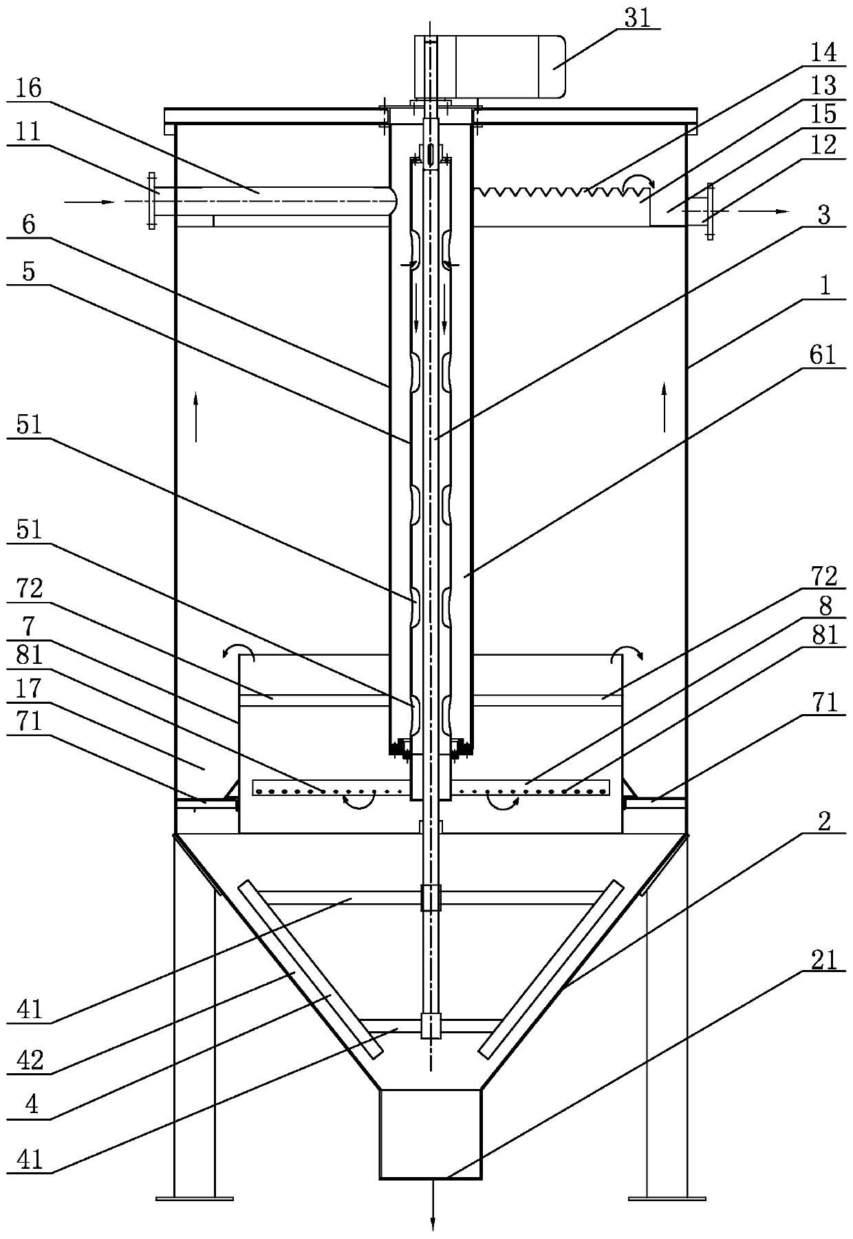
[0025] The improved vertical flow sedimentation tank of embodiment 1, as figure 1 As shown, the pool body 1 is included, the pool body 1 is provided with a water inlet 11 and a water outlet 12, the bottom of the pool body 1 is provided with a tapered mud bucket 2 with a large upper part and a smaller bottom part, and a mud scraping device is arranged in the pool body 1. The mud scraping device includes a driving device 31, a central transmission shaft 3 and a scraper, and the central transmission shaft 3 is connected to the output end of the driving device 31. In this embodiment, the driving device 31 adopts a motor, and the motor 31 is installed on the top of the pool body 1. The scraper is fixed on the central transmission shaft 3, and the scraper is located on the inner side of the mud bucket 2. The scraper includes a number of inclined plates 4, and the plurality of inclined plates 4 are fixedly connected with the central transmission shaft 3 through a plurality of connecti...

Embodiment 2

[0028] The difference between the improved vertical flow sedimentation tank of embodiment 2 and embodiment 1 is that in embodiment 2, the lower part of the central cylinder 5 communicates with a water distribution device, and the water distribution device is suspended in the mud turning box 7, using When, the sewage in the central cylinder 5 flows through the water distribution device and enters in the mud turning box 7.

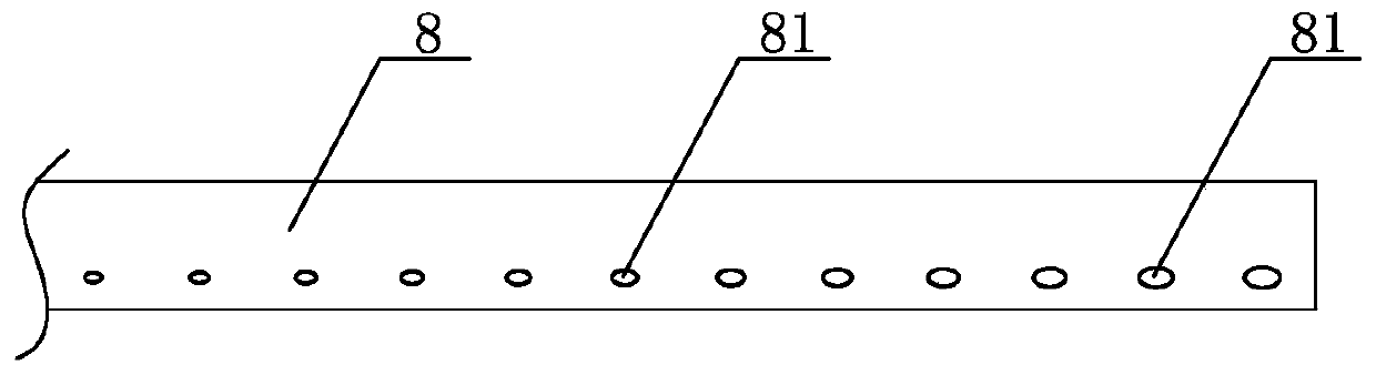
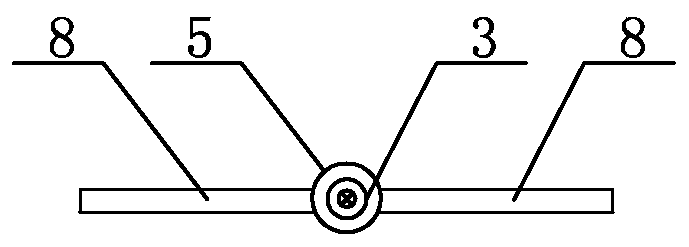
[0029] In Embodiment 2, the water distribution device includes an even number of water distribution pipes 8 arranged horizontally centered on the central transmission shaft 3, and each water distribution pipe 8 is provided with a plurality of water distribution holes 81, and the plurality of water distribution holes 81 are arranged along each The lengthwise direction of the water distribution pipe 8 is arranged at intervals; a plurality of water distribution holes 81 are provided at the bottom of each water distribution pipe 8, and the plurality of water dist...


PUM


Abstract

The invention discloses an improved vertical flow sedimentation tank which comprises a tank body, a water inlet and a water outlet are formed in the tank body, a big-end-up conical sludge hopper is arranged at the bottom of the tank body, a sludge scraping device is arranged in the tank body, the sludge scraping device comprises a driving device, a center transmission shaft and a scraper blade, and the center transmission shaft is connected with the output end of the driving device. The scraper plate is fixed to the center transmission shaft and located on the inner side of the sludge hopper,and a sludge discharging opening is formed in the bottom of the sludge hopper. According to the improved vertical flow sedimentation tank disclosed by the invention, the sludge scraping device is arranged in the tank body, in a sewage treatment process, the driving device can drive the central transmission shaft to slowly rotate, and the scraper plate can scrape and stir sludge in the sludge hopper serving as a sludge concentration area, so that the flowability of the sludge is improved, and the sludge can be continuously and smoothly discharged from the sludge discharging opening; the sludgeblockage condition is avoided, the sludge sedimentation effect is good, the sludge discharge continuity and the sludge discharge efficiency are ensured, and the water quality purification effect is ensured.

Description

technical field [0001] The invention relates to a sewage treatment device, in particular to an improved vertical flow sedimentation tank. Background technique [0002] Sedimentation tank is a common sewage treatment device or system, which has the function of removing suspended solids in water and purifying water quality. The structure of the existing sedimentation tank generally includes a tank body with a water inlet and a water outlet, a settling device is arranged inside the tank body, and a mud collecting bucket is arranged at the bottom of the tank body. After the water flows into the tank body through the water inlet, the sludge settles in the sedimentation device and is collected by the mud collecting bucket, and the purified water is discharged from the water outlet. As disclosed in CN202822888U, a fast horizontal flow high-efficiency sedimentation and separation device comprises an upper rectangular tank body and a lower conical mud collecting bucket. Several rows...

Claims


Application Information

Patent Timeline
Patent Type & Authority Applications(China)
IPC IPC(8): B01D21/06B01D21/18B01D21/20B01D21/24C02F1/52
CPCB01D21/06B01D21/18B01D21/20B01D21/2416B01D21/2444B01D21/245C02F1/52C02F2201/002C02F2303/14
Inventor 俞建德曹霞方向
Owner ZHEJIANG DEAN TECH
Why Eureka
Try Eureka