
Automatic spraying system for fire extinguisher bottle

An automatic spraying and fire extinguisher technology, which is applied in the direction of spraying booths and spraying devices, can solve problems such as inconvenient use, affecting the area of ​​spraying paint, and affecting the production of fire extinguisher bottles, so as to ensure production efficiency, improve automation, and realize automatic feeding and The effect of automatic unloading

Active Publication Date: 2020-02-28
潍坊华宝消防器材有限公司
View PDF15 Cites 10 Cited by
  • Summary
  • Abstract
  • Description
  • Claims
  • Application Information

AI Technical Summary

Problems solved by technology

[0003] The fire extinguisher bottle is an important container for storing fire extinguishing agents. After it is formed, its surface needs to be painted (for example: safety reminders, safety labels, etc.), and it needs to be supported by hangers during the painting process In order to ensure the effect of spray painting, there are two kinds of hangers nowadays, one: it can clamp the outer wall of the bottle body of the fire extinguisher, but this kind of hanger will affect the area of ​​painting; The inner wall is supported, because the clamping part is fixed, and the fire extinguisher bottle needs to be supported. When it enters the fire extinguisher bottle, it needs to "tilt" the rod body so that the clamping part can enter the fire extinguisher bottle, so it is inconvenient to use. defect;
[0004] In addition, today's painting systems require manual assistance in loading and unloading, which greatly affects the production (ie: painting) efficiency of fire extinguisher bottles

Method used


Image

  • Automatic spraying system for fire extinguisher bottle
  • Automatic spraying system for fire extinguisher bottle
  • Automatic spraying system for fire extinguisher bottle

Examples


Embodiment 1

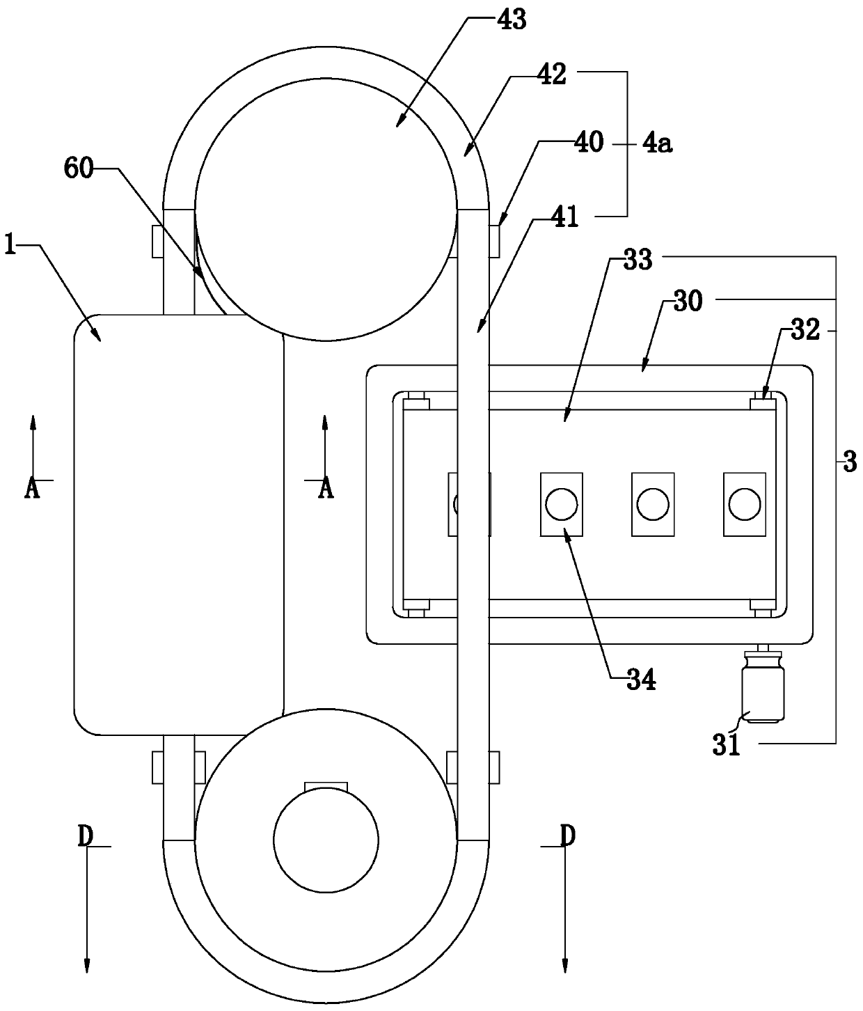
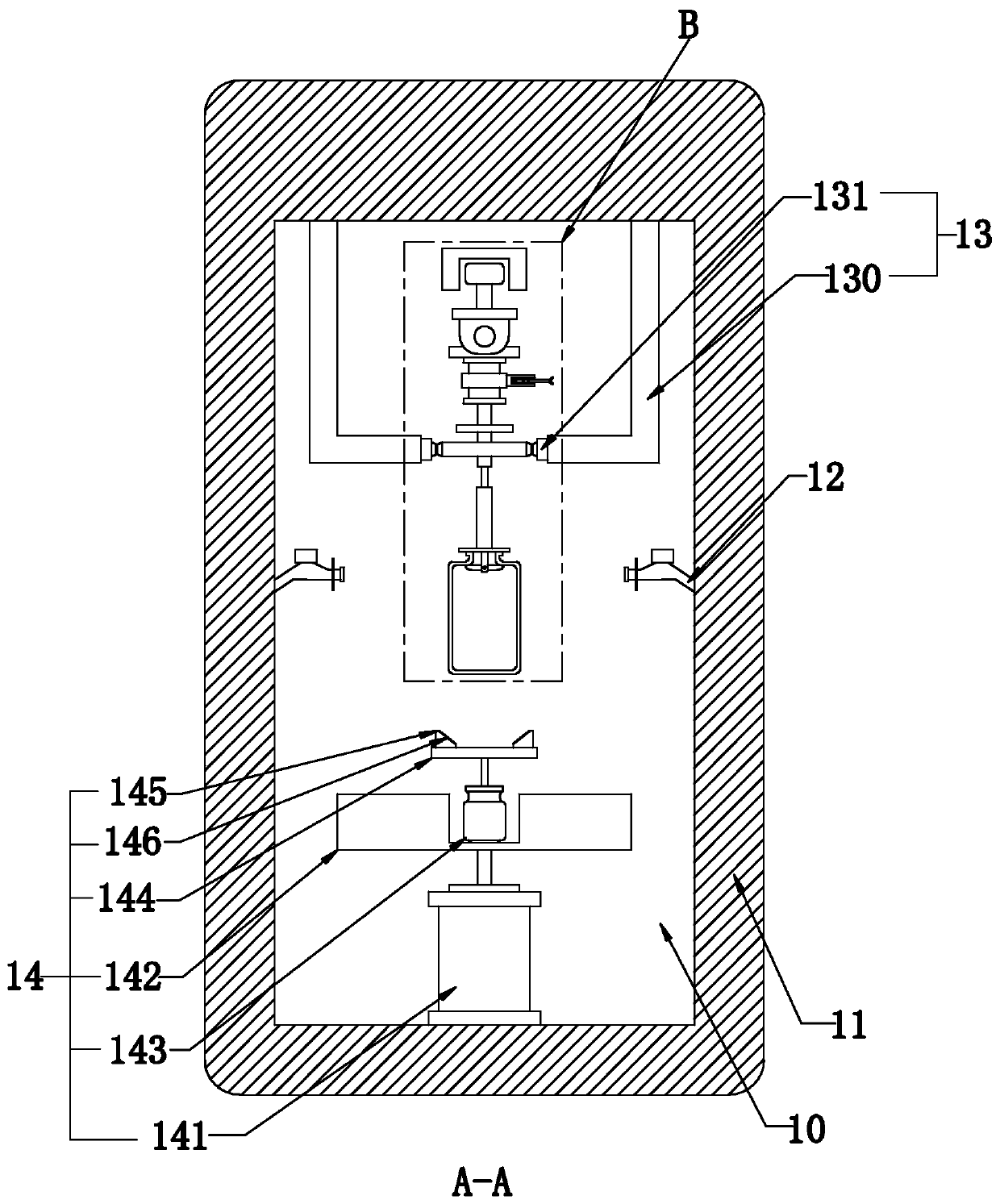
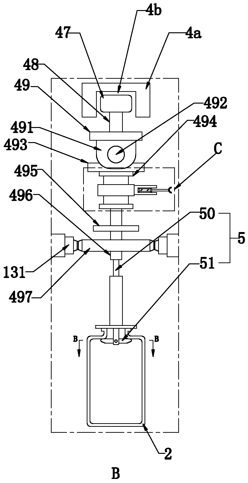
[0036] Such as Figure 1 to Figure 11 As shown, the present invention discloses a fire extinguisher bottle automatic spraying system, including a bottle grasping device for grabbing a fire extinguisher bottle, in a specific embodiment of the present invention, including a spray box 1 with a spray chamber 10, The lower conveying assembly 3 that receives the fire extinguisher bottle body 2 from the bottle grasping device, the upper conveying assembly 4 that is arranged above the lower conveying assembly 3 and is used to convey the fire extinguisher bottle body 2 through the spraying chamber 10, and several upper conveying assemblies 4 and is used to hang the hanger 5 of the fire extinguisher bottle body 2 and the guide rail assembly 6 arranged between the upper conveying assembly 4 and the lower conveying assembly 3 and used to drive the hanger 5 to tilt; wherein, the hanger 5 includes a rod body 50. A support module 51 provided on the rod body 50 that can shrink and bear the we...

Embodiment 2

[0057] Embodiment 2, the difference with embodiment 1 is that

[0058] Such as Figure 12 ~ Figure 13 As shown, in a specific embodiment of the present invention, the support module 51 includes two grooves 51a arranged on the outer wall of the rod body 50 and distributed at equal intervals in the circumferential direction, and two grooves 51a are connected to each groove 51a through the rotating shaft 51b respectively. The support piece 51c that the side groove wall is rotatably connected; wherein, when each support piece 51c is in contact with the notch bottom of the groove 51a, the distance L2 between the free ends of the two support pieces 51c is greater than the diameter of the bottle mouth of the fire extinguisher.

[0059] By adopting the above-mentioned technical scheme: setting each support piece in different grooves can reduce the pressure on the same rotating shaft (that is: the cylindrical pin in Embodiment 1), that is, the pressure of the fire extinguisher bottle t...

Embodiment 3

[0060] Embodiment 3, the difference with embodiment 1 is that

[0061] Such as Figure 14 ~ Figure 15 As shown, in a specific embodiment of the present invention, the support module 51 includes two first telescopic slots 51d arranged on the outer wall of the rod body 50 and distributed at equal intervals in the circumferential direction, and connected with each of the first compression springs 51e The groove bottom of the first telescopic groove 51d is fixedly connected and partly exposes the first telescopic groove 51d and is used to support the support block 51f of the fire extinguisher bottle body 2; wherein, each support block 51f is away from the side end surface of the first compression spring 51e and the bottom end surface thereof The junction is set as an arc surface 51h.

[0062] By adopting the above technical scheme: when the rod body is inserted into the fire extinguisher from the bottle mouth of the fire extinguisher, the support blocks will provide the pressure ...


PUM


Abstract

The invention relates to an automatic spraying system for a fire extinguisher bottle. The automatic spraying system comprises a bottle grabbing device for grabbing the fire extinguisher bottle and ischaracterized by comprising a spraying box, a lower conveying component, an upper conveying component, a plurality of hanging racks and a guide rail component, wherein the spraying box is arranged ina spraying chamber, the lower conveying component is used for receiving the fire extinguisher bottle from the bottle grabbing device, the upper conveying component is arranged above the lower conveying component and used for conveying the fire extinguisher bottle to pass through the spraying chamber, the hanging racks are arranged on the upper conveying component and used for hanging the fire extinguisher bottle, and the guide rail component is arranged between the upper conveying component and the lower conveying component and used for driving the hanging racks to incline; each hanging rack comprises a rod and a supporting module, the supporting module is arranged on the rod, is expandable and is used for bearing the weight of the fire extinguisher bottle, and with the rods as benchmarks,when the supporting modules bear axially upward force, the supporting modules contract and can penetrate into a fire extinguisher bottle opening. The automatic spraying system for the fire extinguisher bottle has the advantages of being convenient to use and high in automation degree.

Description

technical field [0001] The invention relates to the technical field of fire extinguisher spraying, in particular to an automatic spraying system for fire extinguisher bottles. Background technique [0002] A fire extinguisher is a portable fire extinguishing tool. Chemicals are placed in the fire extinguisher to extinguish the fire, which is one of the common fire prevention facilities; [0003] The fire extinguisher bottle is an important container for storing fire extinguishing agents. After it is formed, its surface needs to be painted (for example: safety reminders, safety labels, etc.), and it needs to be supported by hangers during the painting process In order to ensure the effect of spray painting, there are two kinds of hangers nowadays, one: it can clamp the outer wall of the bottle body of the fire extinguisher, but this kind of hanger will affect the area of ​​painting; The inner wall is supported, because the clamping part is fixed, and the fire extinguisher b...

Claims


Application Information

Patent Timeline
IPC IPC(8): B05B16/00B05B13/02
CPCB05B13/0264B05B16/00B05B16/90
Inventor 姜勇华
Owner 潍坊华宝消防器材有限公司
Learn More