Bending device for terminal

A terminal block and bending device technology, which is applied in the manufacture of contact parts, etc., can solve the problems of poor bending effect, affecting the effect of wiring assembly, low efficiency of manual bending, etc., and achieves convenient and fast positioning installation and convenient positioning , good effect

Active Publication Date: 2020-12-08
NANJING COLLEGE OF INFORMATION TECH
View PDF7 Cites 0 Cited by
  • Summary
  • Abstract
  • Description
  • Claims
  • Application Information

AI Technical Summary

Problems solved by technology

[0003] In the prior art, after the inner conductor 410, the outer conductor 420, and the intermediate insulating spacer 430 are assembled, the bending of the inner insertion nose 440 and the first outer insertion nose 450 is generally done manually directly, and the bending is done manually. The effect is not very good, which affects the wiring assembly effect in the later stage, and the manual bending efficiency is low. Therefore, a bending device for this terminal structure is needed, which is convenient for the inner plug nose 440 and the first outer plug nose 450 to be bent at the same time. , while improving work efficiency, it can also improve the bending quality of the nose

Method used


Image

  • Bending device for terminal
  • Bending device for terminal
  • Bending device for terminal

Examples


Embodiment Construction

[0026] The present invention will be further described below in conjunction with the accompanying drawings.

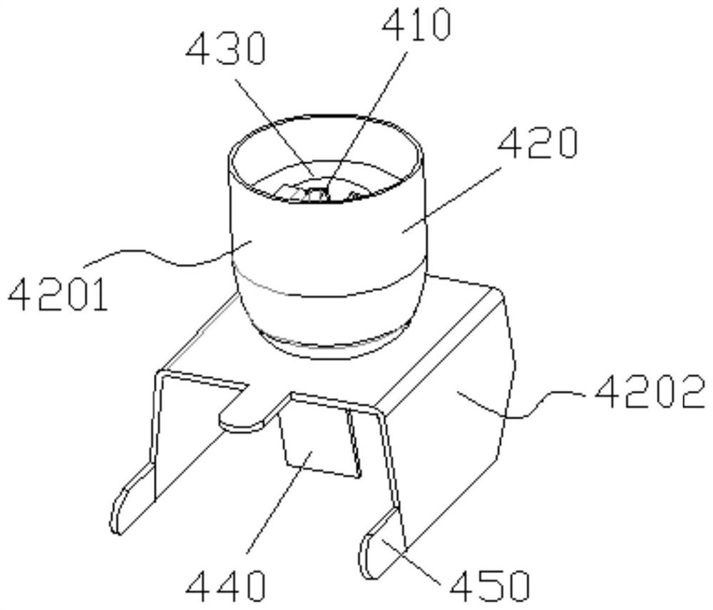
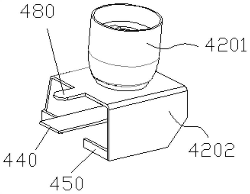
[0027] The present invention is a kind of bending device of connecting terminal, and the specific structure of connecting terminal involved in the present invention is as follows (as figure 1 and figure 2 ):

[0028] The terminal block includes an inner conductor 410, an outer conductor 420 and an intermediate insulating spacer 430. The outer conductor 420 includes a cylindrical sleeve 4201 and a U-shaped plate 4202. The U-shaped plate 4202 includes two sides and a bottom edge. The cylindrical sleeve 4201 The bottom end surface and the bottom edge of the U-shaped plate 4202 are welded and fixed together, and the two sides of the U-shaped plate 4202 are arranged along the axial direction of the cylindrical sleeve 4201 . On both sides of the U-shaped plate 4202, a first external insertion nose 450 is set, and a second external insertion nose 480 is arranged on the bot...


PUM


Abstract

The invention belongs to the technical field of connection terminal production, and particularly discloses a bending device of a connection terminal. The bending device comprises a rack, a first bending air cylinder, second bending air cylinders, an upper supporting mold, a lower supporting mold and a pressing plate. The lower supporting mold is fixed to the rack, the two second bending air cylinders are symmetrically arranged on the left side and the right side of the lower supporting mold, one first bending air cylinder is arranged on the front side of the lower supporting mold, the motion direction of an air cylinder shaft of the first bending air cylinder is perpendicular to the motion directions of air cylinder shafts of the second bending air cylinders, the upper supporting mold is pressed on the lower supporting mold and is engaged with the lower supporting mold, and the pressing plate is inserted on the upper supporting mold. An inner inserting nose and a first outer insertingnoise in the connection terminal can be conveniently subjected to one-time bending simultaneously, work efficiency is high, bending quality is good, the bending device is convenient to dismount and mount, the connection terminal can be rapidly and conveniently positioned, and the use effect is good.

Description

Technical field: [0001] The invention belongs to the technical field of terminal production and relates to a bending device for a terminal. Background technique: [0002] The structure of a terminal block currently on the market is as follows: figure 1 and figure 2 As shown, it includes an inner conductor 410, an outer conductor 420 and an intermediate insulating spacer 430, figure 1 It is a structural diagram of the inner conductor 410, the outer conductor 420 and the intermediate insulating spacer 430 just after assembly, figure 2 It is a final use state diagram of the terminal after the inner plug nose 440 and the first outer plug nose 450 are bent. [0003] In the prior art, after the inner conductor 410, the outer conductor 420, and the intermediate insulating spacer 430 are assembled, the bending of the inner insertion nose 440 and the first outer insertion nose 450 is generally done manually directly, and the bending is done manually. The effect is not very good...

Claims


Application Information

Patent Timeline
Patent Type & Authority Patents(China)
IPC IPC(8): B21D11/00B21D11/22H01R43/16
CPCB21D11/00B21D11/22H01R43/16
Inventor 翟琳
Owner NANJING COLLEGE OF INFORMATION TECH
Why Eureka
Try Eureka