

Control Device, Robot System, And Robot
一种控制装置、机器人的技术,应用在程序控制机械手、机械手、制造工具等方向,能够解决机器人处理的物品破损、难以重启作业等问题
- Summary
- Abstract
- Description
- Claims
- Application Information
AI Technical Summary
Problems solved by technology
Method used
Image

Examples
no. 1 approach
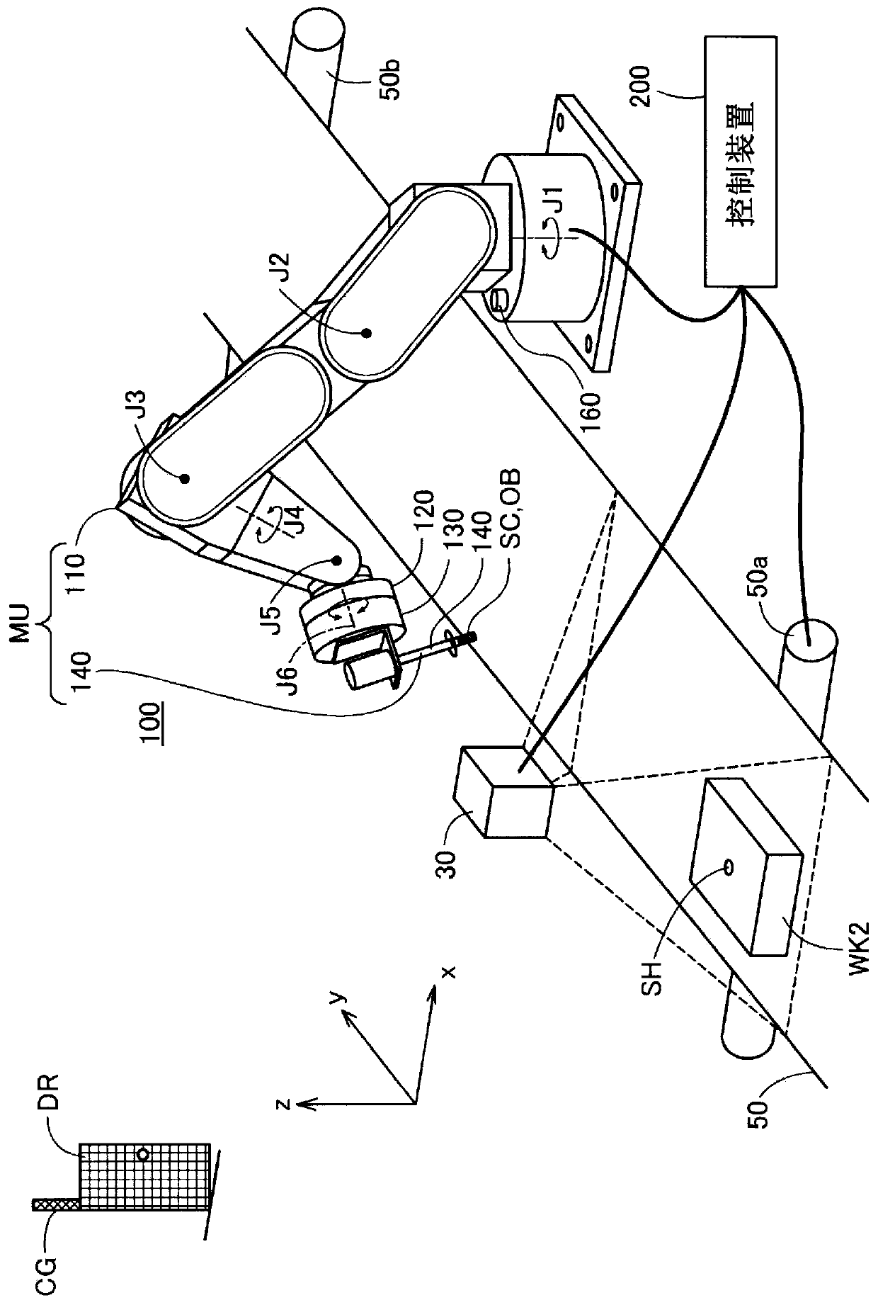
[0027] figure 1 It is an explanatory diagram showing a configuration example of the robot system. This robot system includes a camera 30 , a transport device 50 , a robot 100 , and a control device 200 . The robot 100 and the control device 200 are communicably connected by cables or wirelessly. The surroundings of the work area of the robot 100 are surrounded by safety fences CG. A safety gate DR through which a person can enter and exit is provided on the safety fence CG. A signal indicating the open / close state of the safety door DR is supplied to the control device 200 .
[0028] This robot 100 is a single-arm robot that is used by attaching various end effectors to an arm flange 120 located at the front end of an arm 110 . The arm 110 is provided with six joints J1 to J6. Joints J2, J3, J5 are flexion joints, and joints J1, J4, J6 are torsion joints. On the arm flange 120 located at the front end of the joint J6, various end effectors for performing operations suc...
no. 2 approach
[0060] Figure 7 It is a flowchart showing the execution procedure of the force / position simultaneous control process in the second embodiment. The second embodiment differs from the first embodiment only in a part of the execution steps of the force / position simultaneous control process, and the device structure is the same as that of the first embodiment. Figure 7 and Figure 6 The only difference is that steps S241 to S244 are added after step S240, and other Figure 6 same.
[0061]In steps S241 to S243, the processor 210 monitors the force applied to the movable unit MU, the movement amount of the movable unit MU, and the speed of the movable unit MU, and in the case where at least one of them reaches a predetermined threshold or more Next, go to step S244 and execute error handling. The movement amount of the movable unit MU is a value based on the time point when the position control is stopped in step S210. For example, a process of stopping the robot 100 complet...
no. 3 approach
[0065] Figure 8 It is a flowchart showing the execution procedure of the force / position simultaneous control process in the third embodiment. The third embodiment differs from the first embodiment only in a part of the execution steps of the force / position simultaneous control process, and the device structure is the same as that of the first embodiment. Figure 8 and Figure 6 The only difference is that steps S245 and S246 are added after step S240, and other Figure 6 same.
[0066] In step S245, it is determined whether or not the movement amount of movable unit MU after the position control is stopped in step S210 is equal to or greater than a predetermined threshold. If the amount of movement of the movable unit MU has not reached the predetermined threshold, the process returns to step S220. On the other hand, when the movement amount of the movable unit MU is equal to or greater than the predetermined threshold, the process proceeds to step S246, and returns to st...
PUM
 Abstract
Description
Claims
Application Information