Cutting and crushing device for junked tires

A technology for cutting and crushing waste tires, applied in recycling technology, mechanical material recycling, plastic recycling, etc., can solve the problems of flying out of tire scraps, cleaning of grinding wheels, affecting the cutting effect of tires, etc. Screening rate, the effect of improving the efficiency of crushing and recycling

Pending Publication Date: 2020-02-28
江西维美亚轮胎有限公司
View PDF0 Cites 2 Cited by
  • Summary
  • Abstract
  • Description
  • Claims
  • Application Information

AI Technical Summary

Problems solved by technology

[0003] The present invention aims to solve the problem that tire scraps fly out during the tire cutting and crushing process of the existing tire cutting and crushing device, and the residues of the crushing wheel cannot be cleaned, and the crushing effect of the device is not ideal, and the crushing efficiency is low. Tire cutting and crushing device, the device seals the feeding chamber through a movable plate, avoiding the overflow of the tire feeding chamber during cutting and affecting the cutting effect of the tire, cooling the crushing wheel through a fan, and at the same time, the residual tire stuck on the crushing teeth of the crushing wheel Blow off to avoid residues affecting the crushing effect. The tires are further crushed through the crushing rod. The crushed tires fall into the storage barrel through the leak holes at the bottom and side of the crushing barrel. The crushing barrel is rotated by the turntable to accelerate The tire crushing rate and screening rate improve the crushing and recycling efficiency of the device

Method used


Image

  • Cutting and crushing device for junked tires
  • Cutting and crushing device for junked tires
  • Cutting and crushing device for junked tires

Examples


Embodiment

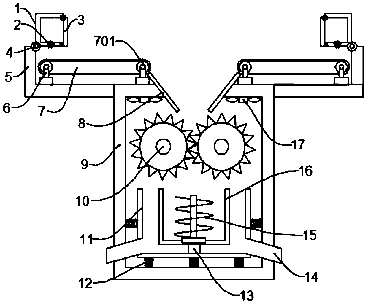
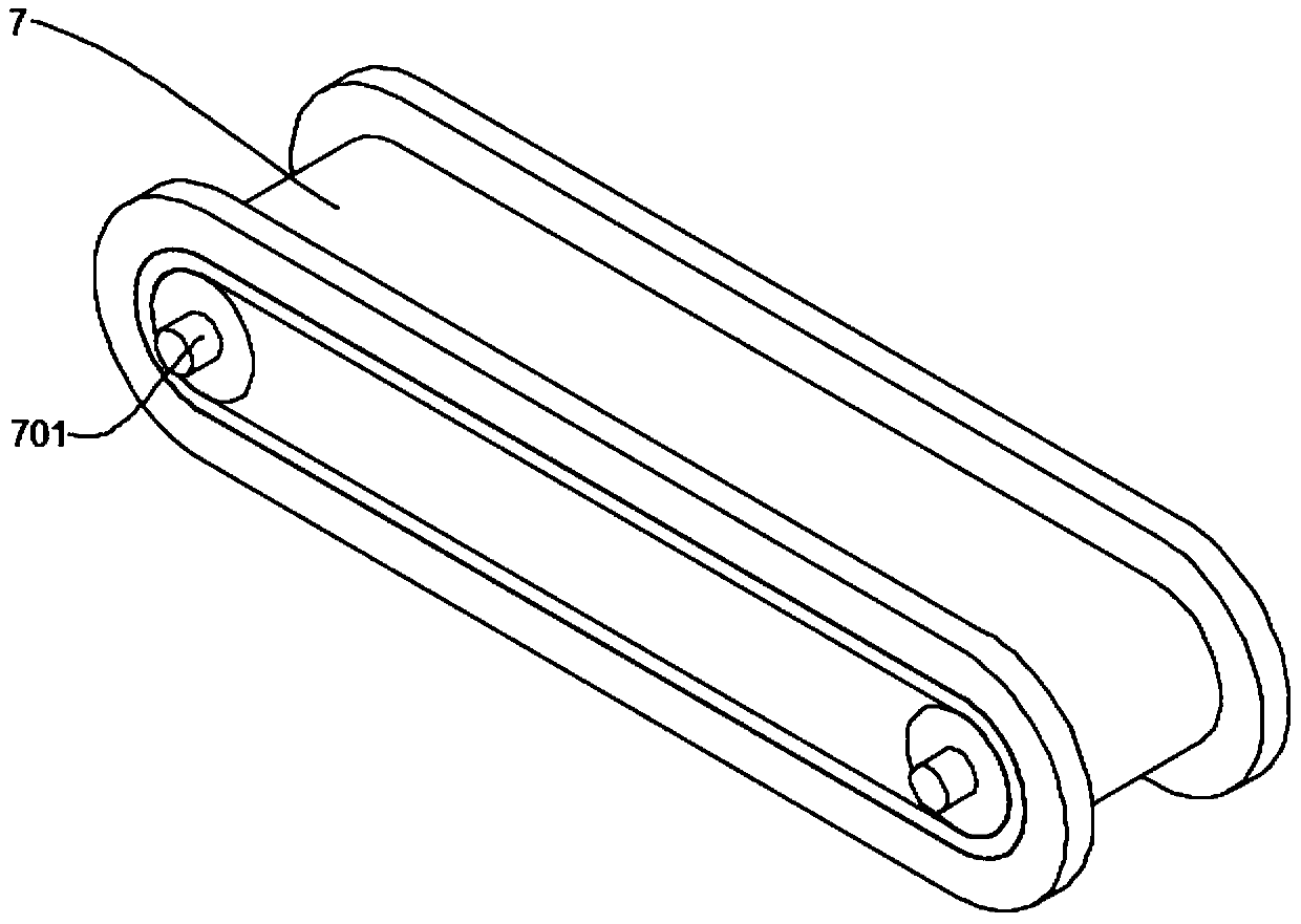
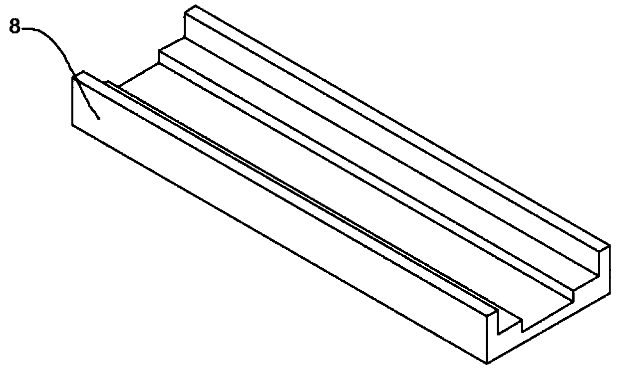
[0020] see Figures 1 to 3 :

[0021] This embodiment provides a further preferred solution for a waste tire cutting and crushing device, which includes a feeding chamber 1 and a crushing chamber 9. A cutting machine 3 is movably connected to the bottom of the inside of the feeding chamber 1, and a movable plate 3 is movably connected to the upper right side of the outside of the feeding chamber 1. The feeding chamber 1 is fixedly provided with a support plate 5 on the outside, a conveyor belt 7 is fixedly connected above the support plate 5, a motor 701 is movably connected to both ends of the inner side of the conveyor belt 7, a base 6 is fixedly connected to the bottom of the motor 701, and both sides of the top opening of the crushing chamber 9 are fixed. A guide plate 8 is connected, and a crushing wheel 10 is movably connected to the bottom of the guide plate 8. A storage barrel 11 is fixedly arranged below the crushing wheel 10. A turntable 13 is embedded in the inner b...


PUM


Abstract

The invention provides a cutting and crushing device for junked tires, and belongs to the technical field of tires. The cutting and crushing device comprises feeding chambers and a crushing chamber. The inner bottom of each feeding chamber is connected with a cutting machine. The upper portion of the right side of the outer portion of each feeding chamber is movably connected with a moving plate.A supporting plate is fixedly arranged on the outer portion of each feeding chamber. The upper portion of each supporting plate is fixedly connected with a conveying belt. The two ends of the inner side of each conveying belt are movably connected with electromotors. The outer portion of the bottom of each electromotor is fixedly connected with a base. According to the device, the feeding chambersare sealed through the moving plates, and the situation that tires overflow when cut in the feeding chambers, and the tire cutting effect is influenced is avoided; crushing wheels are cooled throughfans, meanwhile, tire residues clamped on crushing teeth of the crushing wheels are blown down, and the situation that the crushing effect is influenced by residues is avoided; the tires are further crushed through crushing rods, the crushed tires fall into a storage barrel through leaking holes in the bottom and the side face of a crushing barrel, the crushing barrel is driven by a rotating discto rotate, and the tire crushing rate and screening rate are improved; and the crushing and recovery efficiency of the device is improved.

Description

technical field [0001] The invention relates to the technical field of tires, and more specifically, to a waste tire cutting and shredding device. Background technique [0002] Tires, tires are ground-rolling circular elastic rubber products assembled on various vehicles or machinery. They are usually installed on metal rims, which can support the body, buffer external impact, realize contact with the road surface and ensure the driving performance of the vehicle. Tires inevitably wear and tear during driving, and they will be scrapped after long-term use. During the processing of scrap tires, tires need to be cut and crushed. The existing tire cutting and crushing device will fly out tire waste chips during the tire cutting and crushing process, which cannot The residue of the crushing wheel will be cleaned, the crushing effect of the device is not ideal, and the crushing efficiency is low. Contents of the invention [0003] The present invention aims to solve the proble...

Claims


Application Information

Patent Timeline
IPC IPC(8): B29B17/04
CPCB29B17/04B29B2017/044B29B2017/0476B29B2017/0488Y02W30/52Y02W30/62
Inventor 陈云泽艾乐根
Owner 江西维美亚轮胎有限公司
Why Eureka
Try Eureka