Conveying and arranging mechanism of bag arranging machine

A technology of sorting mechanism and bag management, applied in the directions of transportation and packaging, automatic control of packaging, packaging, etc., can solve the problems of inconvenient adjustment, deflection or even overturning of packaging bags, influence of subsequent processes, etc., which is beneficial to the bundling process and saves Reliable and effective effect of time and manpower, structure

Pending Publication Date: 2020-02-28
浙江创派智能科技有限公司
View PDF0 Cites 2 Cited by
  • Summary
  • Abstract
  • Description
  • Claims
  • Application Information

AI Technical Summary

Problems solved by technology

[0004] 1. The packaging bags coming out of the bag making machine may output one or more channels according to different raw materials, and the sizes of the packaging bags also have various specifications. The corresponding adjustment of the conveying and sorting equipment requires complicated operations, such as using baffles as For equipment with intervals and branches, it is necessary to disassemble and assemble the partitions of the entire line, and adjust the spacing and quantity, which is time-consuming and laborious
[0005] 2. The existing conveying and sorting equipment generally adopts plane conveying. During the conveying process, the packaging bags are easily deflected or even turned over by external influences, which will affect the subsequent process, especially for small and thin packaging bags. In addition, stacked bags are often unable to be neat in all directions
[0006] 3. The packaging bags coming out of the bag making machine often have defective packaging bags due to raw materials or manufacturing problems. Manual removal is inefficient and easy to cause mistakes. The existing removal method is through the entrance of the conveying equipment. An air jet device is installed on the top to make the defective product drop before it enters the packaging bag. However, there are many problems in this method: there is a certain error rate, and it may not be possible to effectively remove the defective product, especially for some sizes and weights. Large packaging bags; in addition, to ensure the removal effect, there needs to be a certain gap between the bag making machine and the conveying and finishing equipment. Packaging bags of different sizes and weights have different optimal gaps, so calculation and adjustment are required before production, and the operation is troublesome , even under the optimal clearance, it is impossible to prevent defective products from entering the conveying and sorting mechanism or qualified products from falling from the clearance; in addition, the airflow generated by the air jet will have an impact on the front and rear packaging bags
[0007] 4. The position of the feeding and discharging direction of the conveying and finishing equipment needs to correspond to the front and rear equipment. The adjustment of the feeding and discharging direction of the existing conveying and sorting equipment is inconvenient, and even the entire device needs to be moved, which is not conducive to automated production

Method used


Image

  • Conveying and arranging mechanism of bag arranging machine
  • Conveying and arranging mechanism of bag arranging machine
  • Conveying and arranging mechanism of bag arranging machine

Examples


Embodiment 1

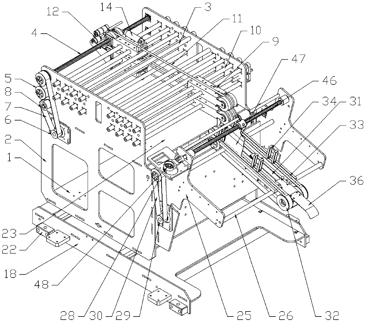
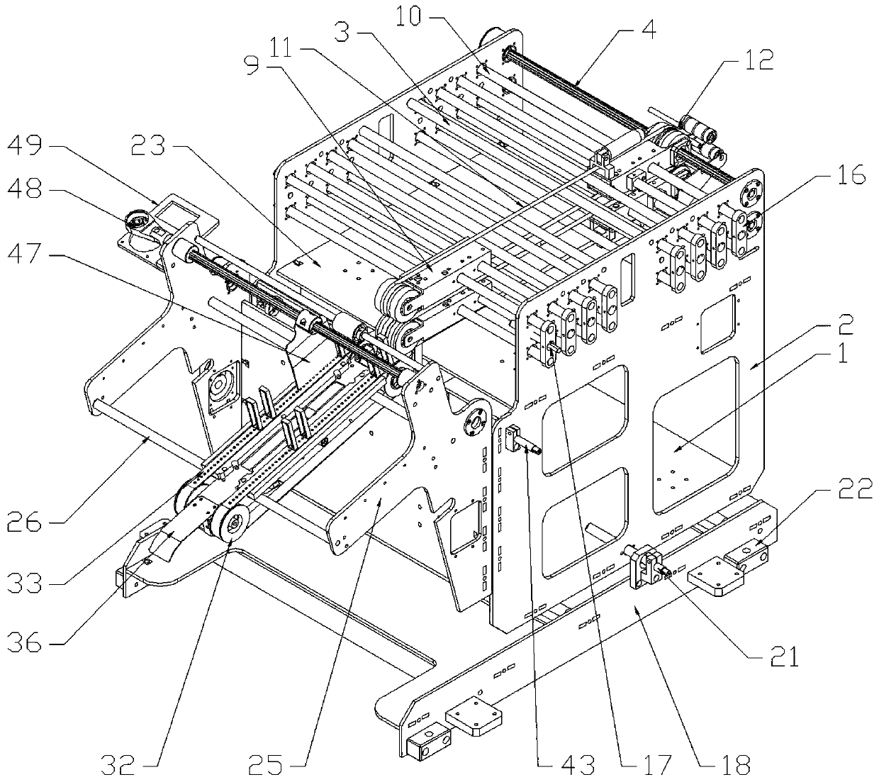
[0055] Embodiment one: if Figure 1-8 As shown, a conveying and sorting mechanism of a bag unscrambling machine is used for sorting and transporting packaging bags, including two parallel sorting wall panels 25, which are supported by a certain number of optical axes a26 between the sorting wall panels. The front end frame of the wallboard 25 is provided with a drive shaft a27, and one end of the drive shaft a27 is connected with a synchronous pulley a28. connect. combine Figure 9-11 As shown, at least one finishing and conveying assembly is provided between two finishing wallboards 25, and the finishing and conveying assembly includes an aluminum tube beam 31, and at least two installation holes a31.1 are arranged on the aluminum tube beam 31, and the aluminum tube beam 31 The front is high and the rear is low on the optical axis a26. The two sides of the front and rear ends of the aluminum tube beam 31 are respectively equipped with synchronous conveying wheels 32. The fr...

Embodiment 2

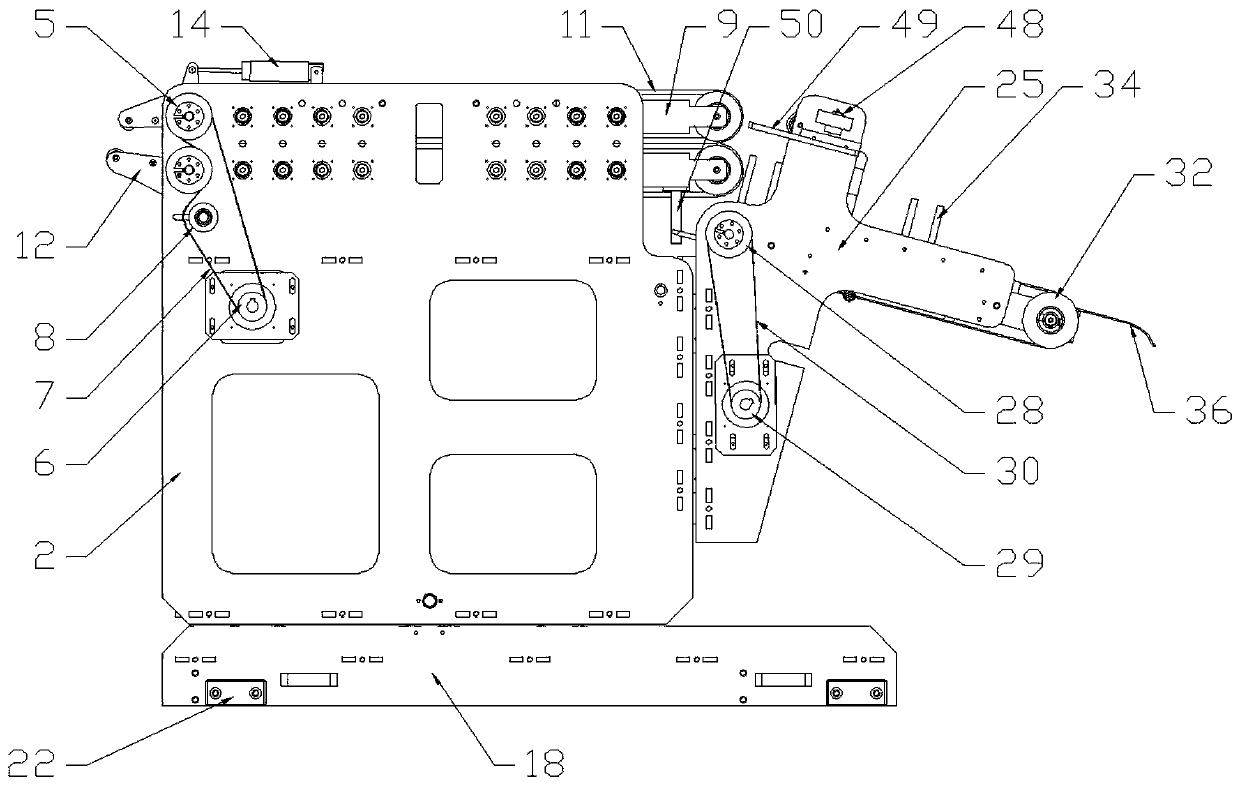
[0057] Embodiment 2: Combination Figure 4-8 As shown, on the basis of Embodiment 1, a vertical first baffle 38 is arranged at the front end of the finishing wall panel 25, a vertical second baffle 39 is arranged on the front side of the first baffle 38, and a vertical second baffle 39 is arranged on the rear side of the second baffle 39. The side is provided with at least two vertical linear guide rails a40, the front side of the first baffle plate 38 is provided with several sliders a41, the middle of the second baffle plate 39 is provided with an opening 39.1, and the second baffle plate 39 front side at the opening 39.1 A vertical adjusting screw a42 is provided, and a horizontal operating rod 43 is also provided on the front side of the second baffle plate 39. The ends of the adjusting screw a42 and the operating rod 43 are provided with mutually meshing bevel gears 44, and the adjusting screw A42 is provided with a nut 45, and the nut 45 passes through the opening 39.1 a...

Embodiment 3

[0058] Example Three: Combining Figure 1-3 As shown in and 12-17, on the basis of Embodiment 2, a conveying mechanism is arranged on the front side of the finishing wallboard 25, and the conveying mechanism includes a bottom plate 1 and conveying wallboards 2 on both sides, and a certain amount of light passes between the conveying wallboards 2. Supported by the shaft b3, the second baffle 39 is fixed on the rear end of the conveying wallboard 2. The front end of the conveying wallboard 2 is provided with two parallel transmission shafts b4 up and down. The transmission shaft b4 can be a spline shaft, and one end of the transmission shaft b4 is connected There is a synchronous belt pulley b5, and a driving wheel b6 connected to the motor is fixed on the conveying wallboard 2. The synchronous belt wheel b5 and the driving wheel b6 are connected through a synchronous belt b7 and the synchronous belt b7 is connected to the two synchronous pulleys b5 in reverse. Wherein, a tensio...


PUM


Abstract

The invention discloses a conveying and arranging mechanism of a bag arranging machine. The conveying and arranging mechanism can be used for arranging and conveying packaging bags, and comprises twoarranging wall plates which are parallel to optical shafts and supported by the optical shafts, a transmission shaft a is erected at the front ends of the optical shafts, one end of the transmission shaft a is connected with a synchronous pulley a, and a driving wheel a connected with a motor is fixed to each arranging wall plates; and at least one arranging conveying assembly is arranged, the arranging conveying assembly comprises an aluminum tube beam, the aluminum tube beam is erected on the optical shafts a in a front-higher and rear-lower mode, the two sides of the front end and the rearend of the aluminum tube beam are provided with synchronous conveying wheels correspondingly, and the transmission shaft a passes through the two synchronous conveying wheels at the front end. An oscillating shaft is arranged, at least one pair of oscillating plates are connected with the oscillating shaft, an eccentric shaft and a shaft sleeve are arranged at one end of the oscillating shaft, andan oscillating motor is arranged on one sides of the arranging wall plates. According to the conveying and arranging mechanism, the number and height of the arranging conveying assembly body can be adjusted as needed, adjusting is very convenient, the structure is suitable for packaging bags with various sizes, the stability of conveying and arranging is guaranteed, and the packaging bags are guaranteed to be neat.

Description

technical field [0001] The invention relates to the technical field of packaging bag manufacturing equipment, in particular to a conveying and sorting mechanism of a bag unscrambling machine. Background technique [0002] After the packaging bag is manufactured in the bag making machine, before entering the binding process, there is generally a process of conveying and sorting. The production speed of the existing bag making machine is very fast. If this process is manually operated, the efficiency is low and the cost is high, and it cannot be matched with the manufacturing process. The production speed of the bag machine. [0003] The conveying and sorting of packaging bags is also operated by equipment, but the existing equipment has certain defects: [0004] 1. The packaging bags coming out of the bag making machine may output one or more channels according to different raw materials, and the sizes of the packaging bags also have various specifications. The corresponding...

Claims


Application Information

Patent Timeline
Patent Type & Authority Applications(China)
IPC IPC(8): B65B57/04
CPCB65B57/04
Inventor 蔡永斌蒋武林
Owner 浙江创派智能科技有限公司
Why Eureka
Try Eureka