Garbage can placing device

A technology for placing devices and trash cans, applied in trash cans, garbage conveying, garbage collection, etc., can solve the problems of occupying municipal roads, affecting the community environment, and easy breeding of flies in garbage, so as to reduce the floor space and reduce the harm. , the effect of convenient export

Active Publication Date: 2020-02-28
ANHUI JIANGSHAN MACHINERY
View PDF5 Cites 3 Cited by
  • Summary
  • Abstract
  • Description
  • Claims
  • Application Information

AI Technical Summary

Problems solved by technology

[0002] In the application of garbage management based on the community as a unit, it has been relatively maturely promoted in the community properties of our country. The domestic garbage generated by the community units is collected by the garbage bins placed in the community, and the property service personnel will collect the full garbage regularly. The trash cans are transferred to the designated community trash can placement area, and then municipal staff operate the garbage compression truck to regularly collect the garbage in the trash bin placement area, and then complete the garbage recycling operation of a single community; the existing technology center, The area where the trash cans are placed in the community is limited by the municipal roads in the community. It is necessary to obtain the consent of the municipal department in advance before delineating the area where the trash cans are placed. After the trash can is placed in the designated area, it will take up a lot of municipal roads or the area where the trash can is placed, and when the temperature is high, the garbage in the trash can is extremely easy to breed flies, seriously affecting the community environment

Method used


Image

  • Garbage can placing device
  • Garbage can placing device
  • Garbage can placing device

Examples


Embodiment Construction

[0035] In order to make the objects and advantages of the present invention clearer, the present invention will be described in detail below in conjunction with the examples. It should be understood that the following words are only used to describe one or several specific implementation modes of the present invention, and do not strictly limit the protection scope of the specific claims of the present invention. As used herein, the terms "parallel" and "perpendicular" are not limited to their strict geometric definitions, but include reasonable and inconsistent tolerances for machining or human error;

[0036] Below in conjunction with the whole community garbage can processing system, the garbage can placement device of the present invention is described in detail:

[0037] Below in conjunction with accompanying drawing, the community refuse bin processing system of the present invention is described in detail:

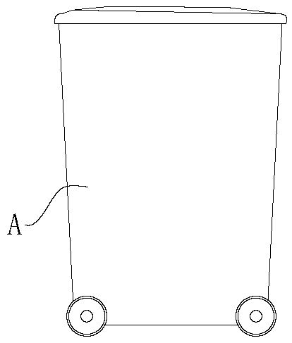
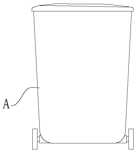
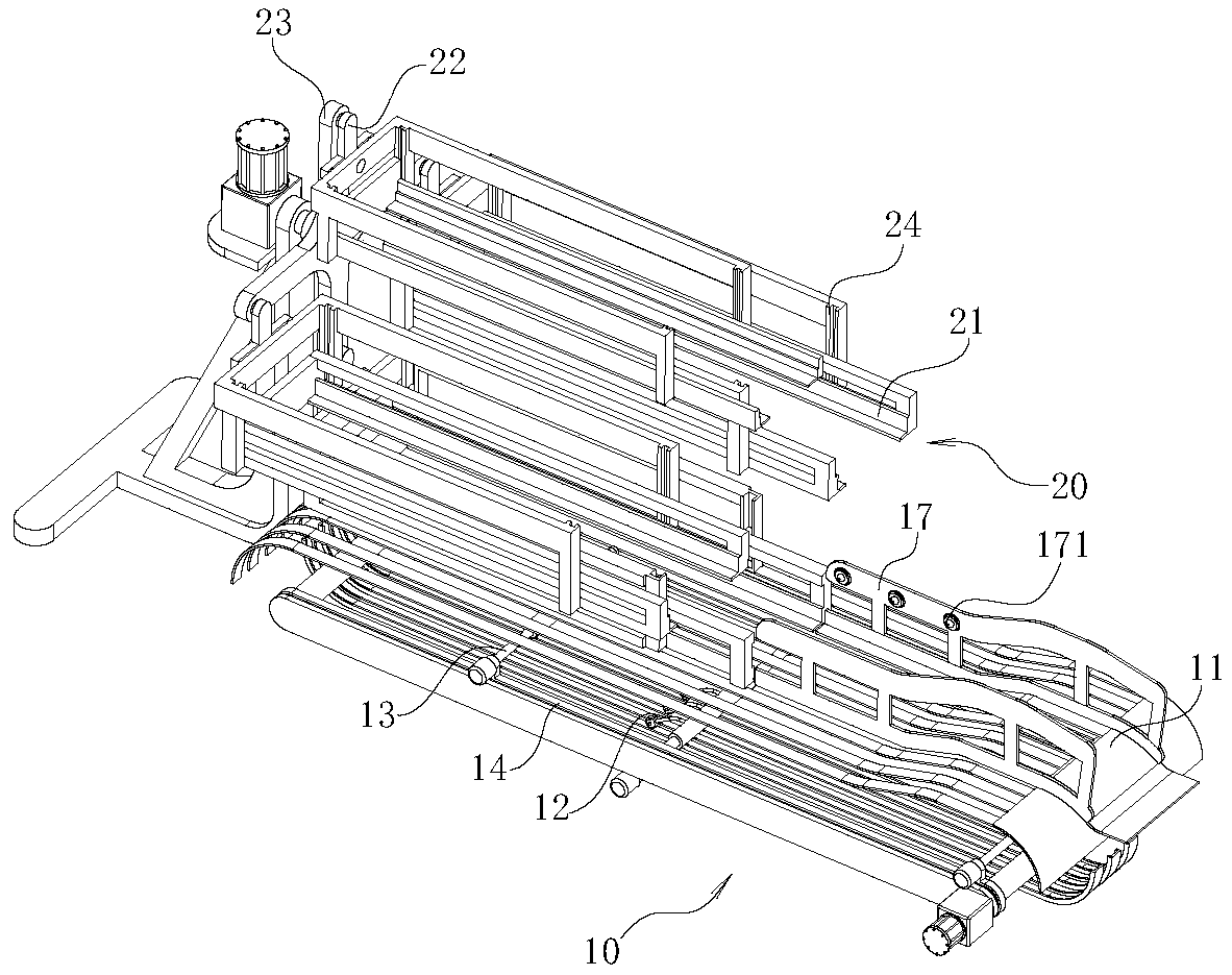
[0038] A community garbage can processing system, comprising ...


PUM


Abstract

The invention relates to a garbage can placing device. The garbage can placing device comprises a garbage can guide-in device, wherein an outlet of the garbage can guide-in device is jointed with an inlet of the garbage can placing device; the garbage can placing device comprises storage framed which are flush to a guide-in rail outlet of the garbage can guide-in device; the storage frames are rotatably arranged on supporting rotary arms through rocker arms; the multiple groups of supporting rotary arms are arranged in a spaced mode in a peripheral direction; a power unit drives the supportingrotary arms to rotate, and a rotary shaft is horizontally arranged; the power unit drives the supporting rotary arms to rotate, and is linked with the rocker arms to rotate, so that the storage framewhich is positioned on the lowest side and is filled up with garbage cans lifts, and the opening of the storage rack which is filled up with the garbage cans is always in a vertical upward state, andtherefore, the garbage cans can effectively fill up each storage frame on the supporting rotary arms, the occupied area is reduced to the greatest extent, and the structure of the whole device further can be simplified; and moreover, the garbage cans further can conveniently drop in and drop out, so that use of the whole garbage can processing equipment is simplified.

Description

technical field [0001] The invention relates to the technical field of garbage disposal equipment, in particular to a garbage can placement device. Background technique [0002] In the application of garbage management with the community as the unit, it has been relatively maturely promoted in the community properties of our country. The domestic garbage generated by the community units is collected by the garbage bins placed in the community, and the property service personnel will collect the full garbage regularly. The trash cans are transferred to the designated community trash can placement area, and then the municipal staff operate the garbage compression truck to regularly collect the garbage in the trash bin placement area, and then complete the garbage recycling operation of a single community; the existing technology center, The area where the garbage cans are placed in the community is limited by the municipal roads in the community. It is necessary to obtain the ...

Claims


Application Information

Patent Timeline
Patent Type & Authority Applications(China)
IPC IPC(8): B65F9/00B65F5/00B65F1/14
CPCB65F1/1473B65F5/00B65F9/00
Inventor 余晓彬
Owner ANHUI JIANGSHAN MACHINERY
Why Eureka
Try Eureka