
Automatic sludge biogas production device

A biogas device and automatic production technology, applied in biological sludge treatment and other directions, can solve the problems of inability to realize automatic liquid discharge and liquid inflow, reduce the production of biogas, and reduce the utilization rate of sludge, so as to avoid the low production of biogas. Effect

Inactive Publication Date: 2020-02-28
曲颖
View PDF0 Cites 0 Cited by
  • Summary
  • Abstract
  • Description
  • Claims
  • Application Information

AI Technical Summary

Problems solved by technology

[0002] In urban life, a large amount of sludge will be produced in urban rivers. At the same time, with the continuous improvement of environmental equipment, the continuous improvement of environmental treatment equipment has been further promoted. Among the current environmental treatment equipment, the treatment of sludge Most of the equipment is compression equipment, which can remove the water in the sludge and then further process the dried sludge, so as to achieve the utilization of sludge. Although sludge drying can achieve a certain utilization effect, the sludge contains a large amount of Therefore, the utilization rate of sludge will be further reduced by drying sludge treatment. In the current process of using sludge to produce biogas, most of the sludge is stored in a centralized manner, and the sludge is further processed after biogas is generated. , although the process of making biogas from sludge can be solved by means of centralized storage, there are still the following problems:
[0003] The process of automatic liquid discharge and liquid intake cannot be realized through traditional sludge biogas equipment. At the same time, due to the centralized storage of a large amount of biogas slurry, the production of biogas is further reduced. There will be a lot of attachments on the surface, which will further reduce the utilization rate of the biogas digester

Method used


Image

  • Automatic sludge biogas production device
  • Automatic sludge biogas production device
  • Automatic sludge biogas production device

Examples


Embodiment Construction

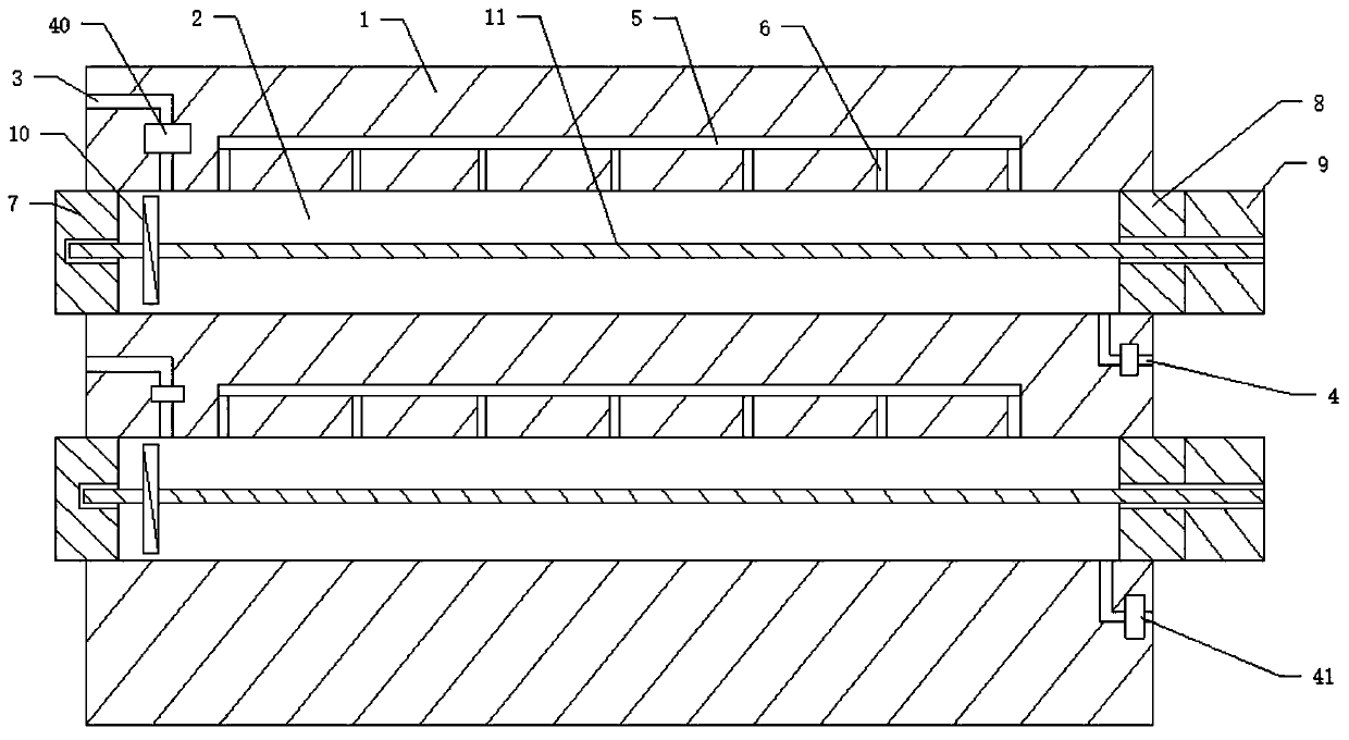
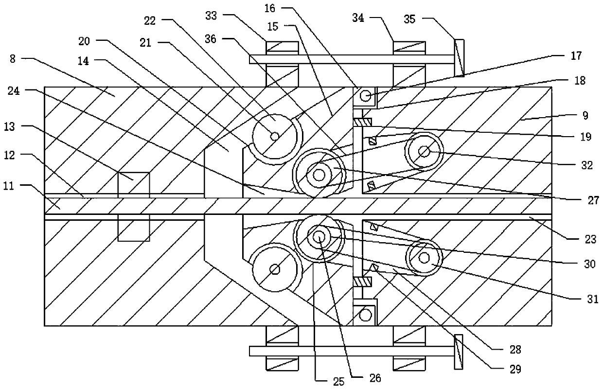
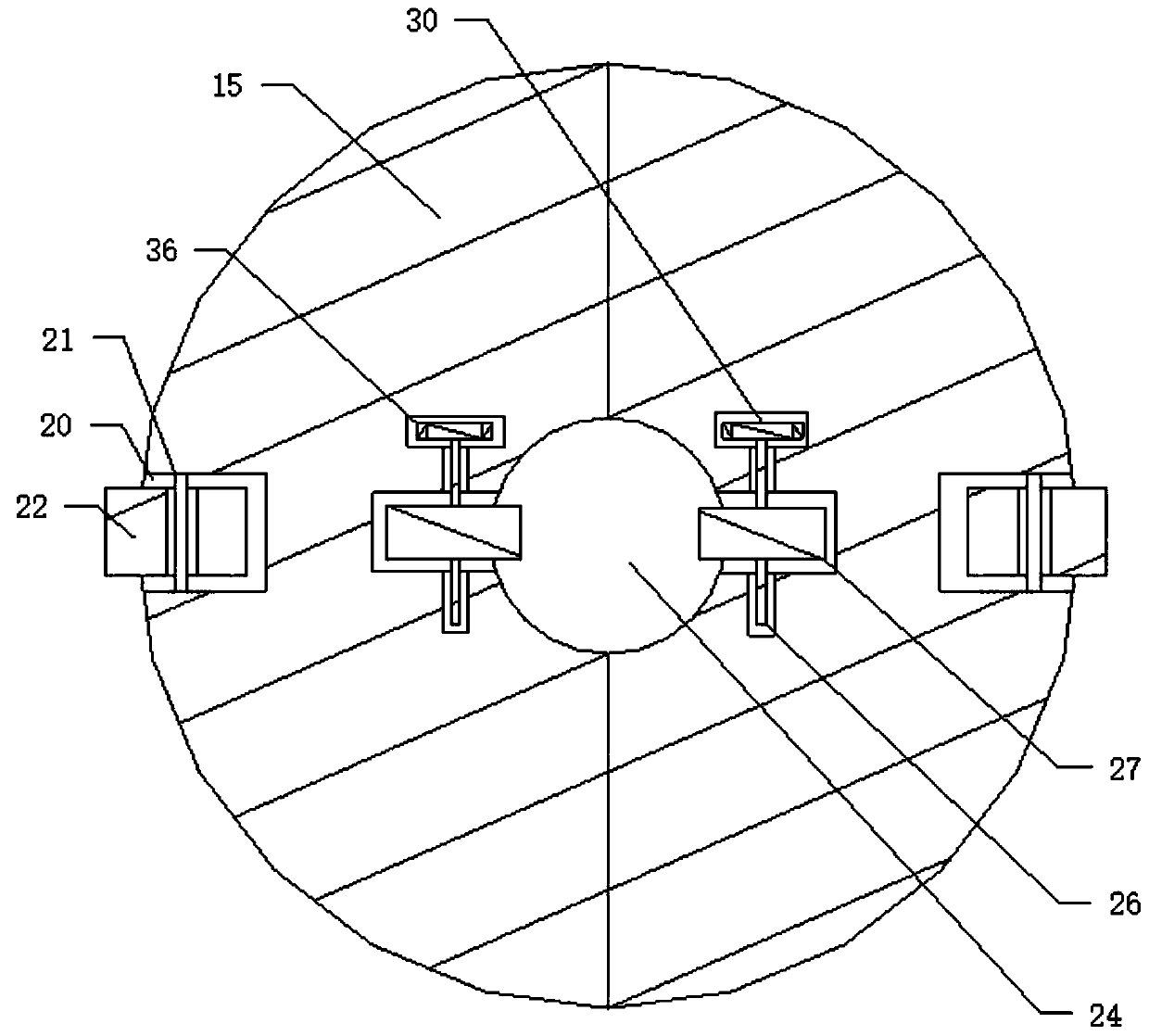
[0033] Such as Figure 1 to Figure 7 As shown, a sludge automatic biogas production device includes a body 1, and the body 1 is provided with a plurality of biogas inner cavities 2, and one end of the biogas inner cavity 2 is respectively provided with a first end 7, The other end of the biogas inner cavity 2 is respectively provided with a second end 8, and a sliding pull rod 11 is respectively arranged in the biogas inner cavity 2, and a sealing push plate 10 is respectively arranged at the end of the pull rod 11 , the sealing push plate 10 and the biogas inner chamber 2 are in a sealed connection, and the second ends 8 are respectively provided with a power end 9, and the power ends 9 respectively control the sliding of the pull rods 11.

[0034] A plurality of biogas inner cavities 2 are provided on the body 1, and the number of biogas inner cavities 2 can be set according to the needs of the design. The biogas inner cavity 2 is a cavity, and one end of the biogas inner ca...


PUM


Abstract

The invention discloses an automatic sludge biogas production device which comprises a machine body, a plurality of biogas inner cavities are formed in the machine body, a first end is arranged at oneend of each biogas inner cavity, a second end is arranged at the other end of each biogas inner cavity, and a sliding pull rod is arranged in each biogas inner cavity. The end part of each pull rod is respectively provided with a sealing push plate, the sealing push plate is in sealing connection with the biogas inner cavity, the second end is respectively provided with a power end, the power endrespectively control the pull rod to slide, the machine body is respectively provided with a liquid inlet hole correspondingly communicated with the biogas inner cavity, and the liquid inlet hole iscommunicated with the biogas inner cavity. The machine body is provided with a row of branch air pipes correspondingly communicated with the biogas inner cavities, and the branch air pipes can generate biogas through sludge in the biogas inner cavities and then further collect the biogas, so that the purpose of automatically preparing the biogas is achieved.

Description

technical field [0001] The invention relates to a sludge treatment device, and specifically designs an automatic sludge biogas production device, in particular to an automatic sludge biogas production device capable of automatically producing biogas from sludge liquid. Background technique [0002] In urban life, a large amount of sludge will be produced in urban rivers. At the same time, with the continuous improvement of environmental equipment, the continuous improvement of environmental treatment equipment has been further promoted. Among the current environmental treatment equipment, the treatment of sludge Most of the equipment is compression equipment, which can remove the water in the sludge and then further process the dried sludge, so as to achieve the utilization of sludge. Although sludge drying can achieve a certain utilization effect, the sludge contains a large amount of Therefore, the utilization rate of sludge will be further reduced by drying sludge treatme...

Claims


Application Information

Patent Timeline
Patent Type & Authority Applications(China)
IPC IPC(8): C02F11/04
CPCC02F11/04
Inventor 曲颖
Owner 曲颖
Learn More