
A cooling system for a screw air compressor

A heat dissipation system and air compressor technology, applied in the direction of rotary piston/oscillating piston pump components, mechanical equipment, machines/engines, etc., can solve problems such as high energy consumption, impact on equipment operation, and poor cooling effect. To achieve the effect of reducing the service life, improving the heat dissipation effect, and facilitating the opening and closing operation

Active Publication Date: 2021-05-04
深圳市比亚美塑胶模具有限公司
View PDF4 Cites 0 Cited by
  • Summary
  • Abstract
  • Description
  • Claims
  • Application Information

AI Technical Summary

Problems solved by technology

The traditional screw air compressor usually uses a fan to blow air on the machine. The screw machine has a large volume and high energy consumption. Due to the position of the fan, it is easy to form a hot spot in a part of the machine, resulting in poor cooling effect.
And the screw air compressor is usually set inside the box for protection. When the screw air compressor needs to be operated, the door on the side of the box usually needs to be dismantled to achieve the heat dissipation effect, but the screw air compressor is easy to accumulate dust, and a large amount of The dust will affect the operation of the equipment and cause the machine to malfunction

Method used


Image

  • A cooling system for a screw air compressor
  • A cooling system for a screw air compressor
  • A cooling system for a screw air compressor

Examples


Embodiment Construction

[0035] The present invention will be described in further detail below in conjunction with the accompanying drawings.

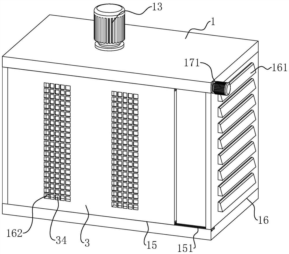
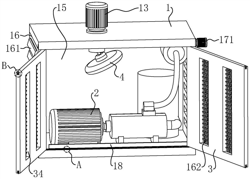
[0036] refer to figure 1 and figure 2 , is a heat dissipation system of a screw air compressor disclosed in the present invention, including an air compressor main body 2, a protective box 1 is installed on the outer side of the air compressor main body 2, and the inner side of the protective box 1 is located above the air compressor main body 2 Rotate is equipped with electric fan 4.

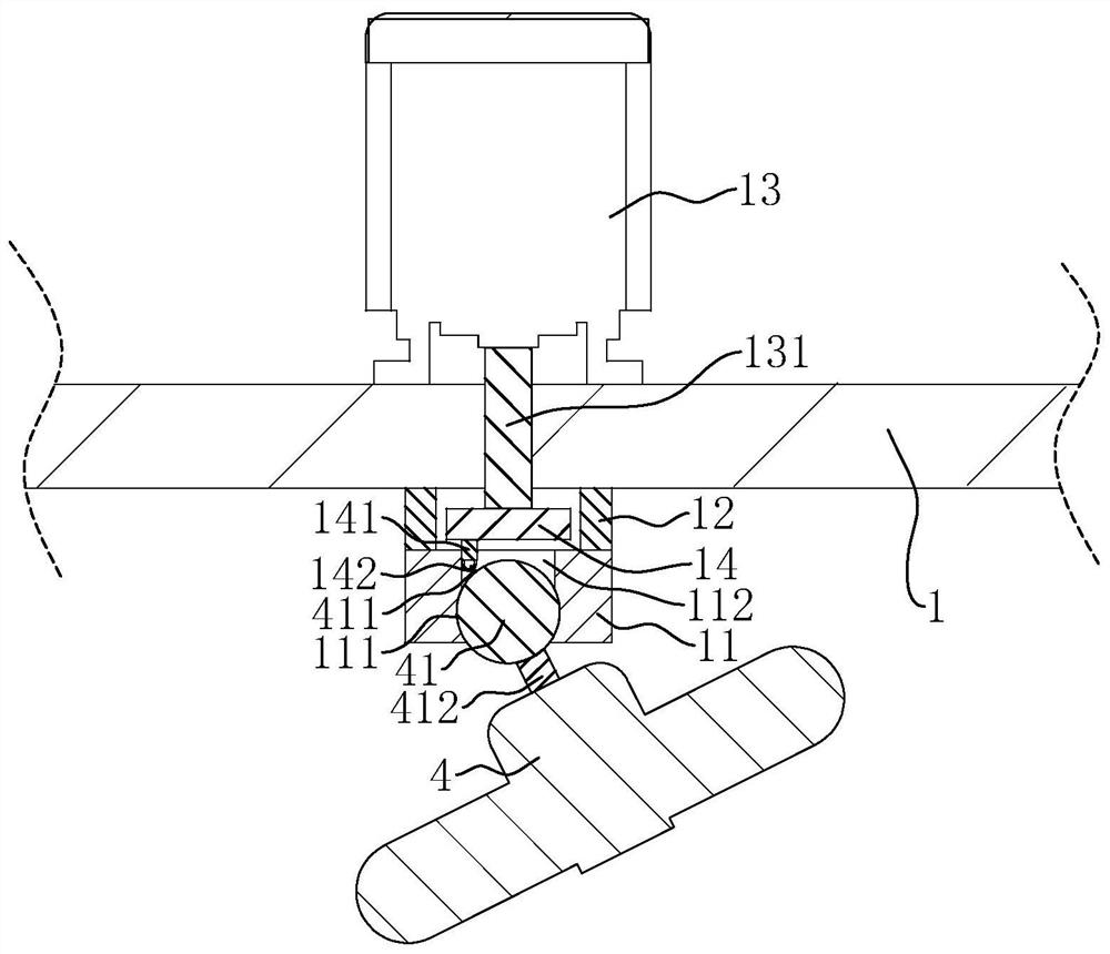
[0037] refer to figure 2 and image 3 , the inner top surface of the protective box 1 is fixed with a mounting seat 11, the mounting seat 11 is connected with the inner top of the protective box 1 through two connecting handles 12, there is a distance between the mounting seat 11 and the inner top of the protective box 1, and the electric fan 4 It is installed on the bottom surface of the mounting base 11 by a twisting mechanism. The twisting mechanism includes a ball hea...


PUM


Abstract

The invention relates to a heat dissipation system of a screw type air compressor, which comprises an air compressor main body and a protection box arranged outside the air compressor main body, an electric fan is arranged in the protection box, and a support is arranged between the electric fan and the protection box Its revolving torsion mechanism, the electric fan is connected with a driving mechanism that drives it to revolve, the opposite two side walls of the protective box are provided with cooling vents, and two staggered and partially overlapping sliding doors are slidably arranged in the cooling vents. A plurality of ventilation holes are opened on the upper part, and when the two sliding doors are far away from each other, the ventilation holes on the two sliding doors are staggered. The driving mechanism is used to drive the electric fan to rotate and blow air, which can blow and cool down the various areas of the screw air compressor and improve the heat dissipation effect; push the two sliding doors so that the ventilation holes of the two sliding doors overlap each other, and the ventilation holes are used for air circulation. The heat dissipation effect is further improved, and at the same time, the sliding door blocks part of the dust and reduces the accumulation of dust.

Description

technical field [0001] The invention relates to the technical field of screw air compressors, in particular to a cooling system for screw air compressors. Background technique [0002] Screw air compressor is an indispensable pneumatic energy source in industrial production, widely used in various industries: textile, steel, oil refining, automobile industry, etc. The traditional screw air compressor usually uses a fan to blow air on the machine. The screw machine has a large volume and high energy consumption. Due to the position of the fan, it is easy to form a hot spot in the machine, resulting in poor cooling effect. And the screw air compressor is usually set inside the box for protection. When the screw air compressor needs to operate, the door on the side of the box usually needs to be dismantled to achieve the heat dissipation effect, but the screw air compressor is easy to accumulate dust, and a large amount of The dust will affect the operation of the equipment an...

Claims


Application Information

Patent Timeline
Patent Type & Authority Patents(China)
IPC IPC(8): F04C29/04F04C29/00
CPCF04C29/00F04C29/04
Inventor 秦升言吴昌平杜果韦耀山秦锦华谢娟
Owner 深圳市比亚美塑胶模具有限公司
Learn More