
Run-flat tire

a run-flat tire and sidewall technology, applied in the field of run-flat tires, can solve problems such as breakage, and achieve the effect of preventing local heat accumulation in the sidewall portion during run-flat running and improving run-flat durability

Active Publication Date: 2019-06-04
SUMITOMO RUBBER IND LTD
View PDF17 Cites 0 Cited by
  • Summary
  • Abstract
  • Description
  • Claims
  • Application Information

AI Technical Summary

Benefits of technology

[0016]The run-flat tire of the present invention is provided in the side inner-cavity surface with the smooth surface which does not have unevenness. The total surface area of the smooth surface is more than 90% of the total area of the side inner-cavity surface. Therefore, local heat accumulation in the sidewall portion during run-flat running is prevented. Consequently, the run-flat durability is improved.BRIEF EXPLANATION OF THE DRAWINGS
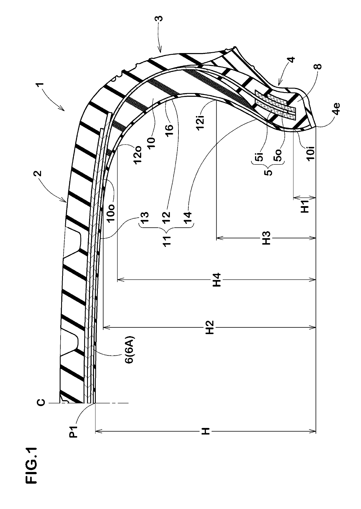
[0017]FIG. 1 a cross sectional view of a run-flat tire showing an embodiment of the present invention
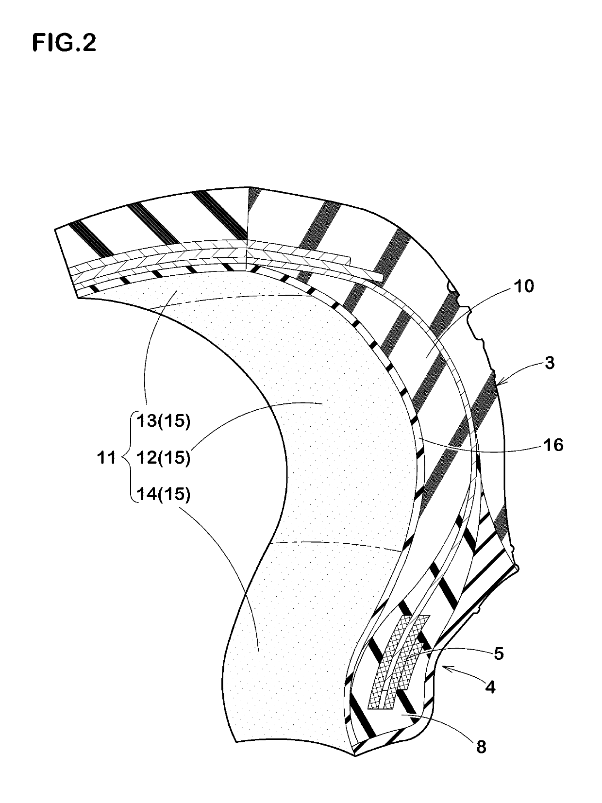
[0018]FIG. 2 a perspective view showing the tire inner-cavity surface of the run-flat tire of FIG. 1
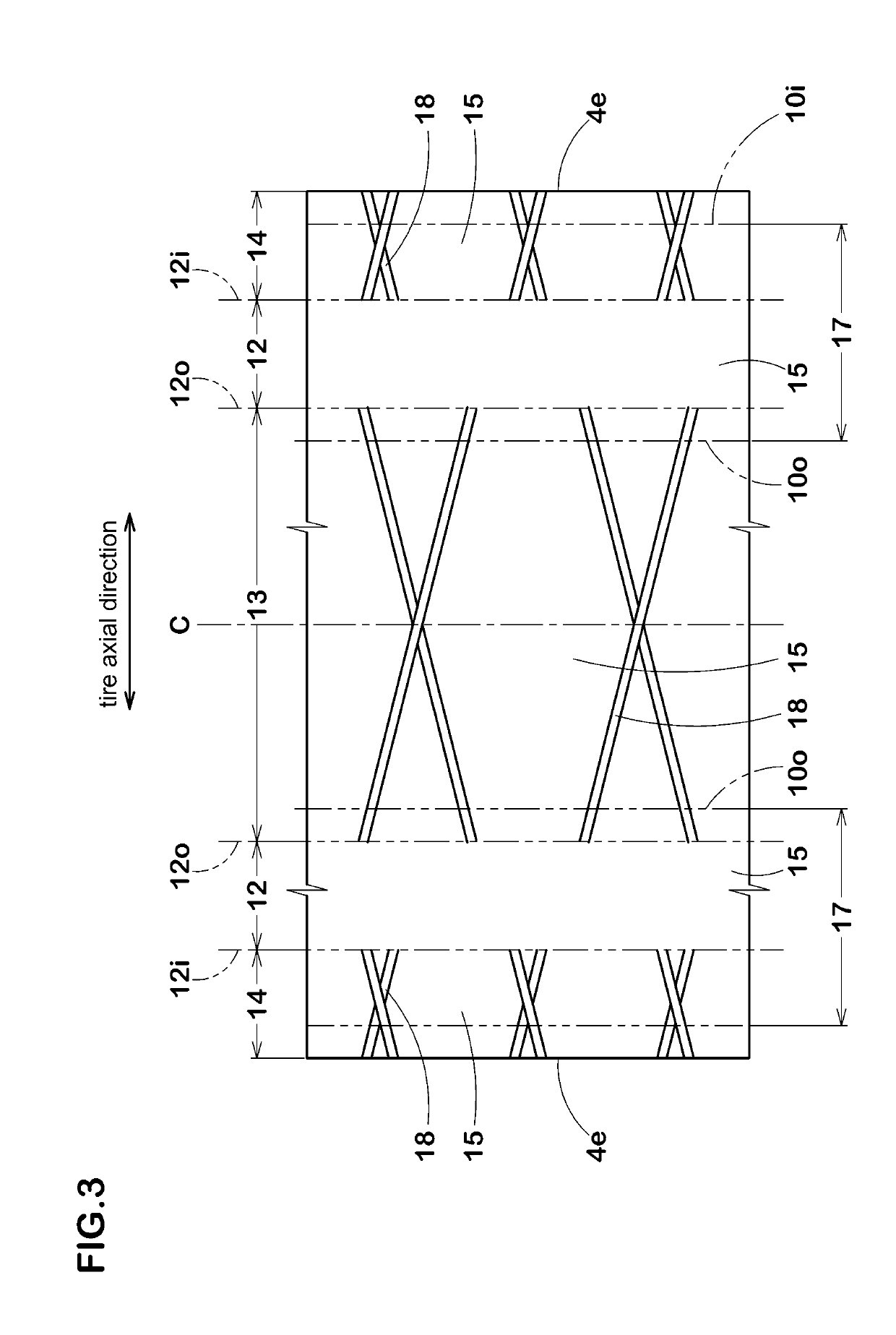
[0019]FIG. 3 a developed plan view of the tire inner-cavity surface of another embodiment
[0021]FIG. 5 a diagram for explaining a step of applying tire constructional members onto the rigid core

Problems solved by technology

If the temperature of the side-reinforcement rubber layer becomes high, breakage occurs.

Method used


Image

  • Run-flat tire
  • Run-flat tire
  • Run-flat tire

Examples


embodiments

[0067]Run-flat tires of 245 / 40R17 for passenger car making up the basic structure of FIG. 1 were experimentally manufactured according to specifications in Table 1, and tested for the run-flat durability.

[0068]The test tires included tires having a tire inner-cavity surface manufactured with a bladder (indicated as A in Table 1), and tires having a tire inner-cavity surface manufactured with the rigid core (indicated as B in Table 1).

[Tire A]

[0069]In the tire inner-cavity surface, convexed parts were formed by vent lines formed on the bladder. The convexed part was like a 0.5 mm height 0.5-1.0 mm width rib.

When the tire inner-cavity surface was developed as shown in FIG. 3, the convexed parts extended, inclining at 0 to 10 degrees with respect to the tire axial direction.

[Tire B]

[0070]The tire inner-cavity surface had no convexed part. In the tire inner-cavity surface of the tire B, membranous burrs were formed.

[0071]Test methods were as follows.

[0072]The test tire was mounted on a ...


PUM

PropertyMeasurementUnit
elastic modulus Eaaaaaaaaaa

Abstract

It is a run-flat tire 1 provided with a carcass 6 extending from a tread portion 2 through a sidewall portion 3 to a bead core 5 in a bead portion 4, and a side-reinforcement rubber layer 10 disposed inside the carcass 6 in the sidewall portion 3 and having a substantially crescent-shaped cross-section. In a tire meridian cross section including the tire rotational axis under a normal state such that the tire is mounted on a normal rim, inflated to a normal internal pressure and loaded with no load, the tire inner-cavity surface 11 includes a side inner-cavity surface 12. A distance in the tire radial direction of the side inner-cavity surface 12 from a bead toe 4e of the bead portion 4 is in a range of 0.4 times to 0.9 times the length H in the tire radial direction of the tire inner-cavity surface 11. The side inner-cavity surface 12 includes a smooth surface 15 which does not have unevenness, and the total surface area of the smooth surface 15 is more than 90% of the total area of the side inner-cavity surface 12.

Description

TECHNICAL FIELD[0001]The present invention relates to a run-flat tire capable of running for a relatively long distance in a punctured state.BACKGROUND ART[0002]A run-flat tire provided in a sidewall portion with a side-reinforcement rubber layer whose cross section is crescent-shaped has been proposed. When the inner pressure is decrease by a puncture, the side-reinforcement rubber layer supports the load of the tire, and the deflection of the tire is prevented. such run-flat tire is able to run for a relatively long distance in a punctured state (hereinafter, referred to by “run-flat running” in some situations).[0003]During run-flat running, deformation and restoration of the side-reinforcement rubber layer occur repeatedly, and the side-reinforcement rubber layer c generates heat. If the temperature of the side-reinforcement rubber layer becomes high, breakage occurs. Accordingly, a run-flat tire in which breakages resulting from heat are hard to occur is desired.[0004]In order ...

Claims


Application Information

Patent Timeline
Patent Type & Authority Patents(United States)
IPC IPC(8): B60C17/00B60C9/02B60C3/00B60C13/00B29D30/12B60C5/12B60C15/00B29D30/20
CPCB60C17/0009B29D30/12B60C3/00B60C5/12B60C9/023B60C15/00B60C15/0018B60C17/0045B60C13/00B60C2017/0063B29D2030/201B60C2013/026B60C9/0207
Inventor SUGIYAMA, NAOKI
Owner SUMITOMO RUBBER IND LTD
Learn More