A high-efficiency dust-removing drying equipment for textile production

A drying equipment and high-efficiency technology, which is applied in drying, drying machines, textiles and papermaking, etc., can solve the problems of increasing processing steps, reducing efficiency, and affecting the quality of fabrics, so as to reduce steps, increase efficiency, and avoid partial heating effect

Active Publication Date: 2021-12-28
临沂边锋自动化设备有限公司
View PDF8 Cites 0 Cited by
  • Summary
  • Abstract
  • Description
  • Claims
  • Application Information

AI Technical Summary

Problems solved by technology

[0003] 1. When the existing textile dryers are in use, hot air is directly injected into the drying chamber, and the injection port for injecting hot air is in a fixed state, which will cause partial drying of the cloth to be dried. Partial drying will affect the quality of the cloth after drying;
[0004] 2. After the fabric is dried, a lot of dust will be generated. If the dust is not treated in time, it will adhere to the fabric. In order to ensure the subsequent quality of the fabric, follow-up dust treatment is required, which increases the processing steps. reduce overall efficiency

Method used


Image

  • A high-efficiency dust-removing drying equipment for textile production
  • A high-efficiency dust-removing drying equipment for textile production
  • A high-efficiency dust-removing drying equipment for textile production

Examples


Embodiment 1

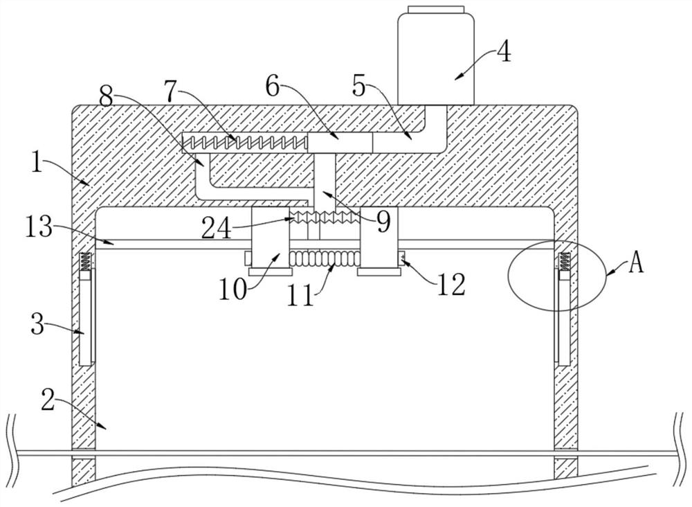
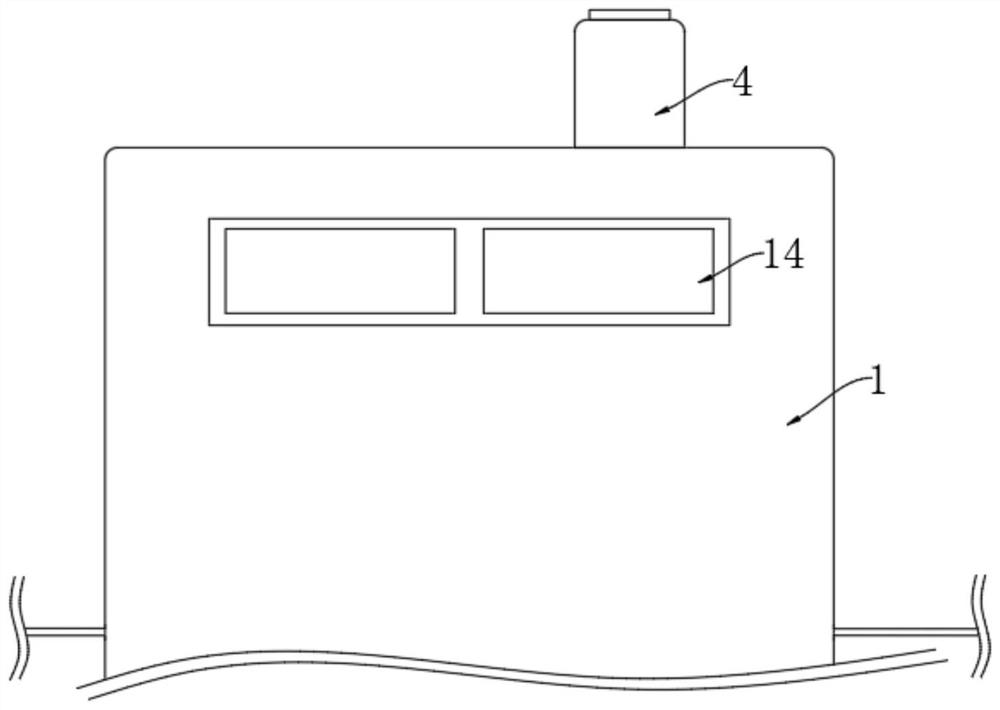
[0023] refer to Figure 1-3 , a high-efficiency dust removal type drying equipment for textile production, including a housing 1, a connecting air duct 5 and a drying chamber 2 are arranged in the housing 1, the connecting air duct 5 is located above the drying chamber 2, and the housing 1 Two vertical cavities 3 are symmetrically arranged inside, and the two vertical cavities 3 are located on both sides of the drying chamber 2, and a sliding door 14 is installed on the front side of the housing 1;

[0024] Blast mechanism, the blower mechanism includes the hot air blower 4 that is installed on the upper end of the housing 1, the air outlet of the hot air blower 4 extends to the space on the right side connecting the air duct 5, the drying chamber 2 is horizontally provided with a slide bar 13, and the bottom of the slide bar 13 The two ends are respectively fixedly connected to the inner walls of both sides of the drying chamber 2, and the sliding rod 13 is provided with two ...

Embodiment 2

[0031] refer to Figure 4-5 , The difference between this embodiment and Embodiment 1 is that the inner walls on both sides of the drying chamber 2 are fixedly connected with fixing plates 23, and the two fixing plates 23 are vertically penetrated with abutment rods 19, and each abutment The rods 19 are all slidably connected to the corresponding fixing plates 23, and each contacting rod 19 is fixedly sleeved with a connecting plate 21, and the lower end of each connecting plate 21 is elastically connected to the upper end of the corresponding fixing plate 23 through the third connecting spring 22, The upper end of each contact rod 19 is fixed with a wedge-shaped block 20, and the slopes of the two wedge-shaped blocks 20 are all facing one side of the corresponding spray head 10. Contact occurs, causing wedge block 20 to move downward.

[0032] In this embodiment, when the two nozzles 10 are moving away from each other, they will come into contact with the corresponding wedge...


PUM


Abstract

The invention discloses a high-efficiency dust-removing type drying equipment for textile production, comprising a casing, wherein a connecting air duct and a drying chamber are arranged in the casing, the connecting air duct is located above the drying chamber, and the casing Two vertical cavities are symmetrically arranged in the body, and the two vertical cavities are located on both sides of the drying chamber. The hot air blower, the air outlet of the hot air blower extends to the space on the right side of the connecting air duct, the drying chamber is horizontally provided with a sliding rod, and the two ends of the sliding rod are respectively fixedly connected with the inner walls on both sides of the drying chamber , and two spray heads are arranged on the sliding rod. When the drying equipment is drying, its nozzle is always in a moving state, which can effectively avoid the occurrence of local drying. At the same time, it is also equipped with a dust removal mechanism, which reduces the steps of drying treatment, thereby increasing the overall work. efficiency.

Description

technical field [0001] The invention relates to the field of textile production, in particular to a high-efficiency dust removal type drying equipment for textile production. Background technique [0002] The textile industry in China is a highly labor-intensive and foreign-dependent industry. China is the largest producer and exporter of textiles and clothing in the world. The continuous and stable growth of textiles and clothing exports is crucial to solving social employment and the sustainable development of the textile industry. It is very important, and drying is an important process of cloth production, which is used to dry undried cloth. For the existing dryers for textile production, in the process of use, there are the following problems: [0003] 1. When the existing textile dryers are in use, hot air is directly injected into the drying chamber, and the injection port for injecting hot air is in a fixed state, which will cause partial drying of the cloth to be dr...

Claims


Application Information

Patent Timeline
Patent Type & Authority Patents(China)
IPC IPC(8): F26B13/02F26B21/00F26B25/06D06G1/00
CPCF26B13/001F26B21/001F26B21/003F26B21/004F26B25/06D06G1/00
Inventor 郑一丁
Owner 临沂边锋自动化设备有限公司
Why Eureka
Try Eureka