Heat source device
a heat source and heat exchanger technology, applied in water heaters, stationary conduit assemblies, sustainable buildings, etc., can solve the problems of fluid to be heated flowing in the heat exchanger being overheated, local heating is likely to occur, and fluid to be heated is likely to be boiling or denaturing, so as to prevent local heating
- Summary
- Abstract
- Description
- Claims
- Application Information
AI Technical Summary
Benefits of technology
Problems solved by technology
Method used
Image
Examples
first embodiment
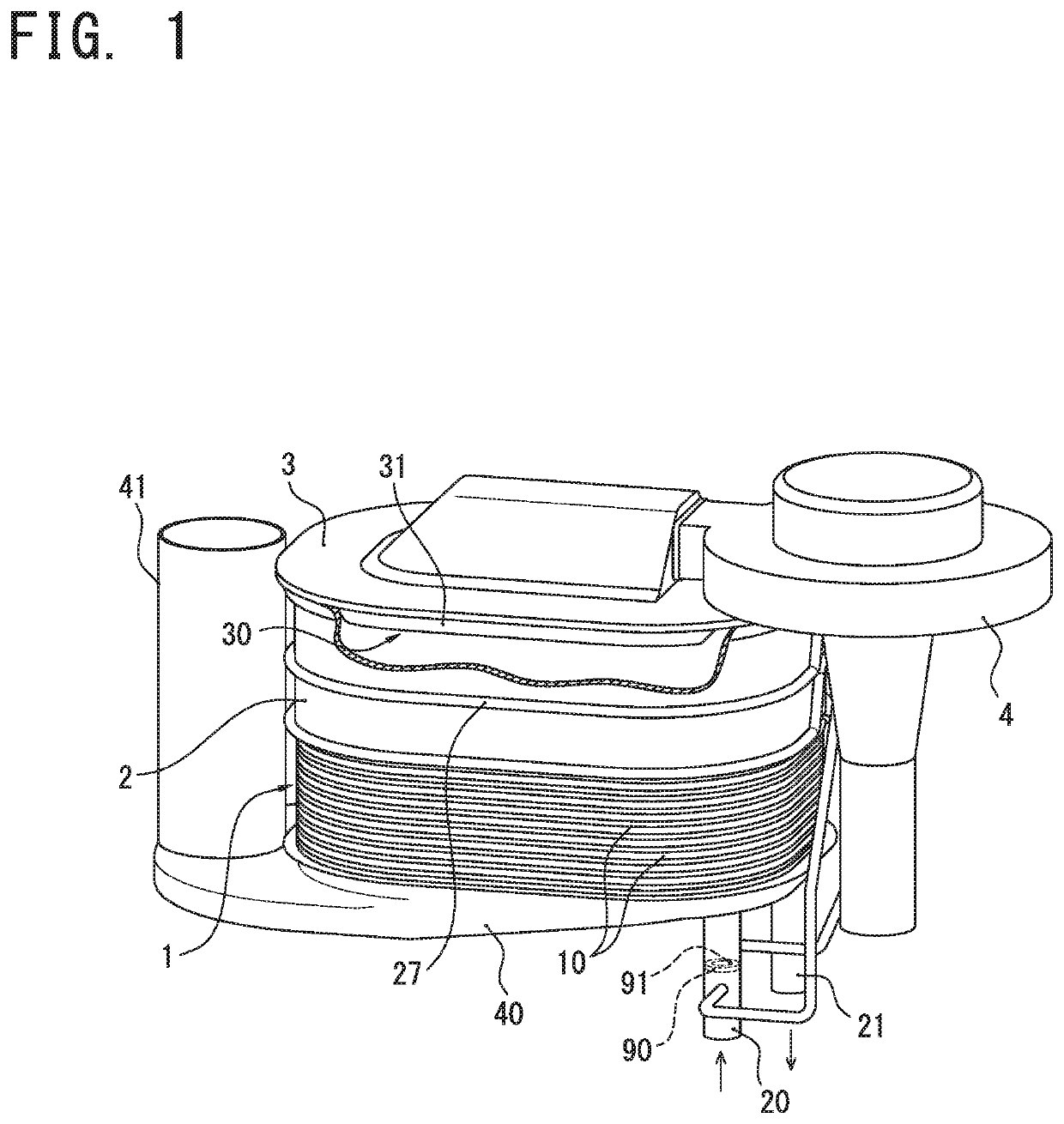
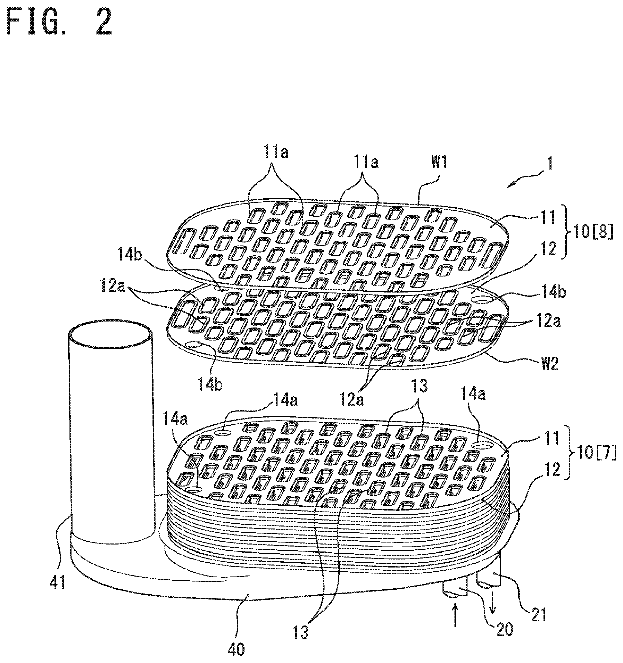
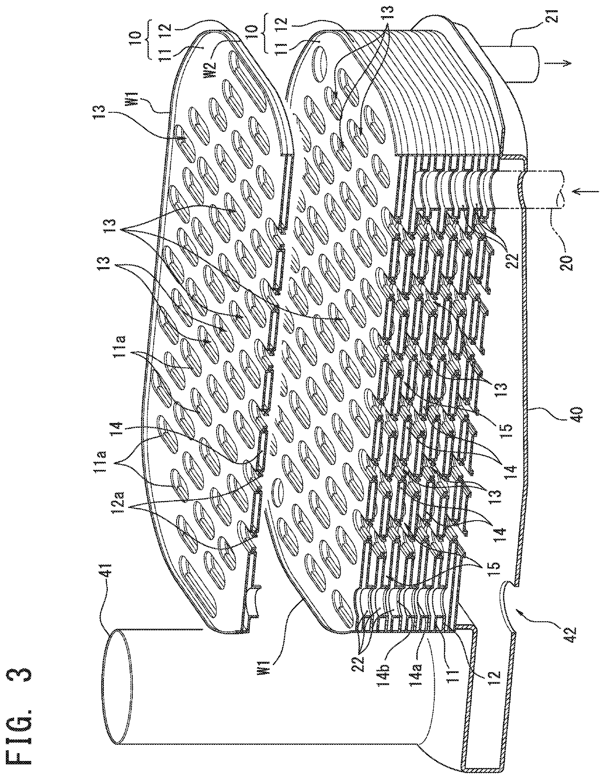
[0023]Hereinafter, referring to drawings, a heat source device according to an embodiment of the present invention will be described in detail. As illustrated in FIG. 1, a heat source device according to the present embodiment is a water heater that heats water (a fluid to be heated) flowing into a heat exchanger 1 from an inlet pipe 20 by combustion exhaust gas generated by a burner 31, and supplies the heated water to a hot water supplying terminal (not illustrated) such as a faucet or a shower through an outlet pipe 21. Although not shown, the water heater is accommodated in an outer casing. Other heating medium (for example, an antifreezing fluid) as the fluid to be heated may be used.
[0024]In this water heater, a burner body 3 constituting an outer shell of the burner 31, a combustion chamber 2, the heat exchanger 1, and a drain receiver 40 are disposed in order from the top. Additionally, a fan case 4 housing a combustion fan for feeding a mixture gas of fuel gas and air into ...
second embodiment
[0046]A heat source device according to the present embodiment has the same configuration as the first embodiment, except that an orifice plate 90 is disposed in an outlet pipe 20, and that upstream and downstream ends of a winding pipe 27 are connected to an outlet pipe 21. Therefore, common elements are assigned the same reference numerals, and their explanations are omitted.
[0047]FIG. 6 is a schematic perspective view showing the heat source device according to the present embodiment. As illustrated in FIG. 6, according to the present embodiment, the orifice plate 90 is disposed in the outlet pipe 21, so that an orifice 91 for throttling a fluid flow path for water is formed in the outlet pipe 21. Further, an upstream branch hole (upstream branch) 92 is opened on a pipe wall of the outlet pipe 21 on an upstream side of the fluid flow path for water more than the orifice 91, and the upstream end of the winding pipe 27 is connected to the upstream branch hole 92. Further, a downstr...
PUM
 Abstract
Description
Claims
Application Information
 - R&D
- Intellectual Property
- Life Sciences
- Materials
- Tech Scout
- Unparalleled Data Quality
- Higher Quality Content
- 60% Fewer Hallucinations
Browse by: Latest US Patents, China's latest patents, Technical Efficacy Thesaurus, Application Domain, Technology Topic, Popular Technical Reports.
© 2025 PatSnap. All rights reserved.Legal|Privacy policy|Modern Slavery Act Transparency Statement|Sitemap|About US| Contact US: help@patsnap.com


