
MicroLED-based display device and display method thereof

A technology of equipment and images, applied in optics, instruments, projection devices, etc., can solve the problems of multi-space, limited service life, high assembly cost, etc.

Inactive Publication Date: 2020-02-28
SHANGHAI NORTH OCEAN PHOTONICS CO LTD
View PDF5 Cites 7 Cited by
  • Summary
  • Abstract
  • Description
  • Claims
  • Application Information

AI Technical Summary

Problems solved by technology

[0006] Specifically, in terms of image sources, passive projections such as LCoS, DLP, and MEMS Scanning Mirror need to use an external light source, so the extra devices need to occupy more space, making it difficult to further reduce the overall volume, and the assembly cost is also high.
LCD and OLED have the problems of low efficiency and brightness, and high power consumption. OLED screen burn-in is still a big problem, because the service life of organic materials is limited, and the stability is very worrying.

Method used


Image

  • MicroLED-based display device and display method thereof
  • MicroLED-based display device and display method thereof
  • MicroLED-based display device and display method thereof

Examples


Embodiment Construction

[0050] The following description serves to disclose the present invention to enable those skilled in the art to carry out the present invention. The preferred embodiments described below are only examples, and those skilled in the art can devise other obvious variations. The basic principles of the present invention defined in the following description can be applied to other embodiments, variations, improvements, equivalents and other technical solutions without departing from the spirit and scope of the present invention.

[0051] Those skilled in the art should understand that in the disclosure of the present invention, the terms "vertical", "transverse", "upper", "lower", "front", "rear", "left", "right", " The orientation or positional relationship indicated by "vertical", "horizontal", "top", "bottom", "inner", "outer", etc. is based on the orientation or positional relationship shown in the drawings, which are only for the convenience of describing the present invention...


PUM


Abstract

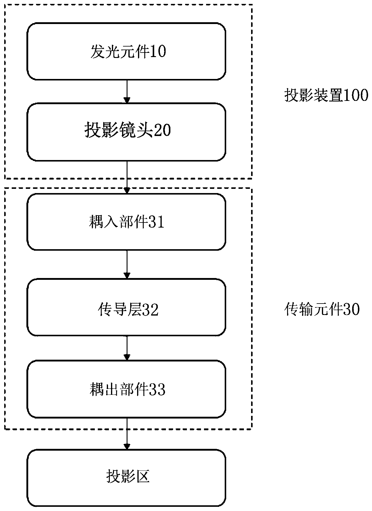
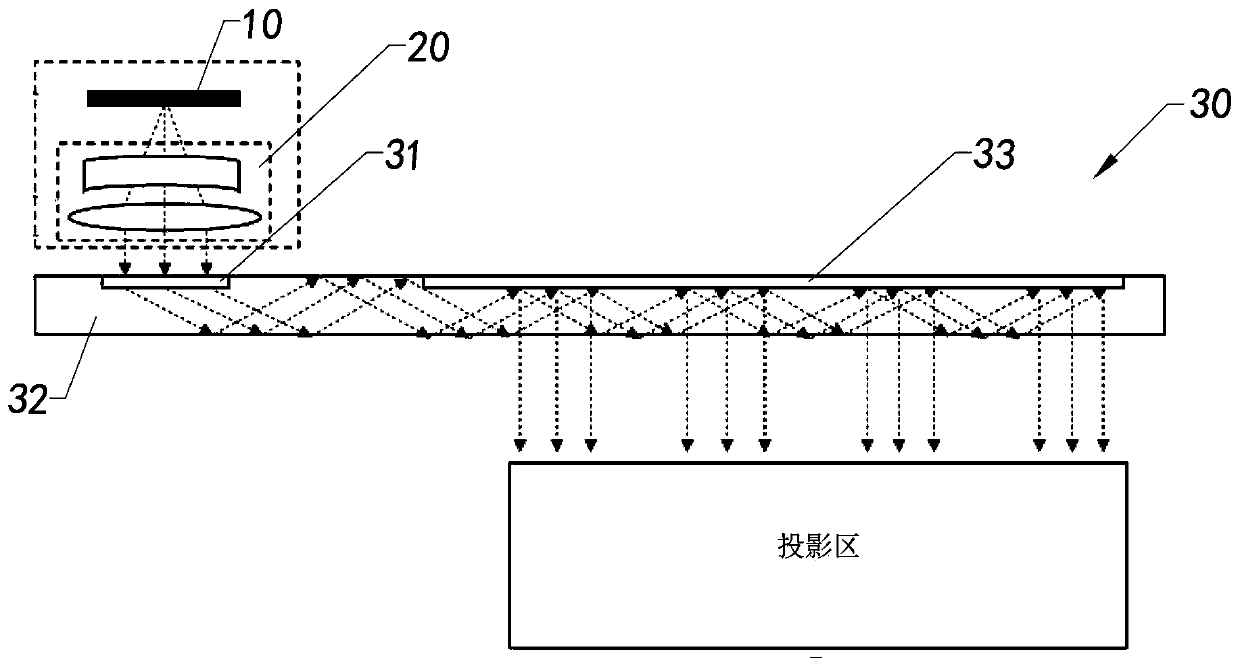
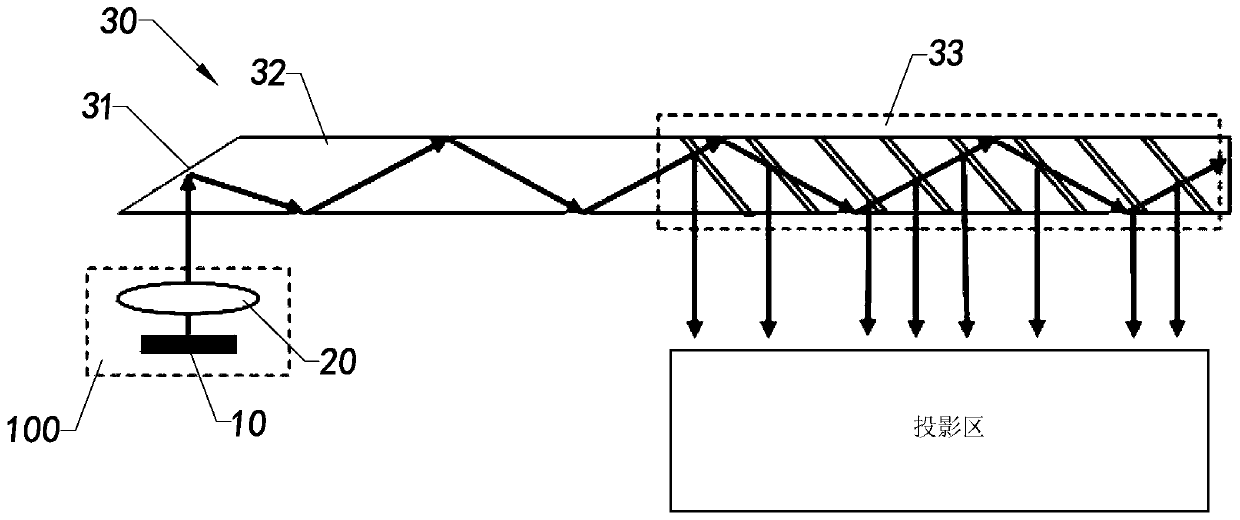
According to the present invention, a MicroLED-based display device for sending an image to a projection area includes a projection device and a transmission element. The projection device emits imagelight based on a MicroLED. The transmission element includes a coupling-in component, a conveying layer and a coupling-out member. The projection device is arranged on the coupling-in component of the transmission element in a manner to align the image light. The coupling-in component receives and guides the image light transmission. The coupling-out component expands and outputs the image lightoutward. The image that enters the conveying layer from the coupling-in component is totally reflected to a light output component, and then is conveyed to the projection area. In addition, the present invention provides a MicroLED-based projection device and a display method thereof. The display device balances on image generation and image transmission to improve the final display quality.

Description

technical field [0001] The invention relates to the field of optical imaging, in particular to a projection device, imaging equipment, and an imaging method. Background technique [0002] Optical imaging devices are indispensable entertainment facilities in modern life. From classic TVs, computers, mobile tablets, to smartphones, smart watches, and augmented reality (Augmented Reality, AR) and virtual reality (Virtual Reality, VR) are all specific optical imaging application devices. Some existing imaging devices are implemented by optical transmission or video transmission. More specifically, for augmented reality technology, the optical transmissive method has become a mainstream implementation method because of its high resolution, no visual deviation, no time delay, and more conveniences in line with social habits. [0003] For imaging devices, the light source and light transmission path are equally important. When the image information of the light-emitting element ...

Claims


Application Information

Patent Timeline
IPC IPC(8): G03B21/20G02B27/01
CPCG03B21/2033
Inventor 孟玉凰楼歆晔黄河林涛
Owner SHANGHAI NORTH OCEAN PHOTONICS CO LTD
Learn More