
Touch display device and manufacturing method thereof

A technology of a touch display device and a manufacturing method, which is applied in lamination devices, chemical instruments and methods, and other household appliances, and can solve problems such as increased production costs, wrinkles in visible areas, and yellowing of lamination, and achieves improved product quality. Yield rate, lower production cost, better touch experience

Inactive Publication Date: 2020-02-28
SHENZHEN CHINA STAR OPTOELECTRONICS SEMICON DISPLAY TECH CO LTD
View PDF4 Cites 6 Cited by
  • Summary
  • Abstract
  • Description
  • Claims
  • Application Information

AI Technical Summary

Problems solved by technology

For large-size touch display devices, a large amount of solid optical glue is required for full-mount technology, which greatly increases the production cost, and there are unfavorable phenomena such as degumming; The lamination method of full lamination technology will cause lamination yellowing problems, bending problems with different expansion and shrinkage, and wrinkle problems in the visible area, etc.

Method used


Image

  • Touch display device and manufacturing method thereof
  • Touch display device and manufacturing method thereof
  • Touch display device and manufacturing method thereof

Examples


Embodiment Construction

[0015] The following describes the embodiments of the present invention in detail. Examples of the embodiments are shown in the accompanying drawings, wherein the same or similar reference numerals indicate the same or similar elements or elements with the same or similar functions. The directional terms mentioned in the present invention, for example: up, down, left, right, front, back, inside, outside, side, etc., are only the directions with reference to the drawings. The following embodiments described with reference to the accompanying drawings and the directional terms used are exemplary, and are only used to explain the present invention, and should not be understood as limiting the present invention.

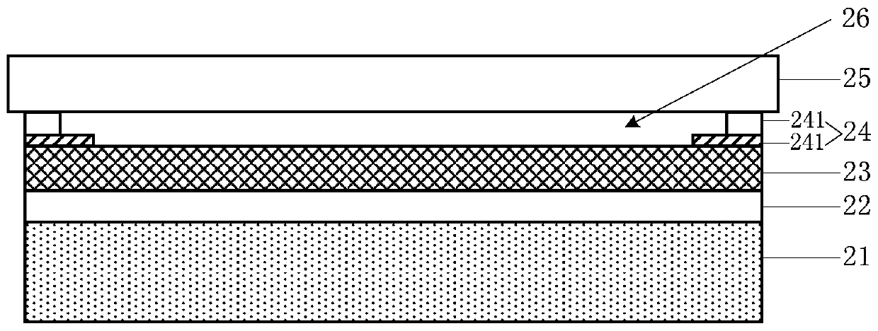
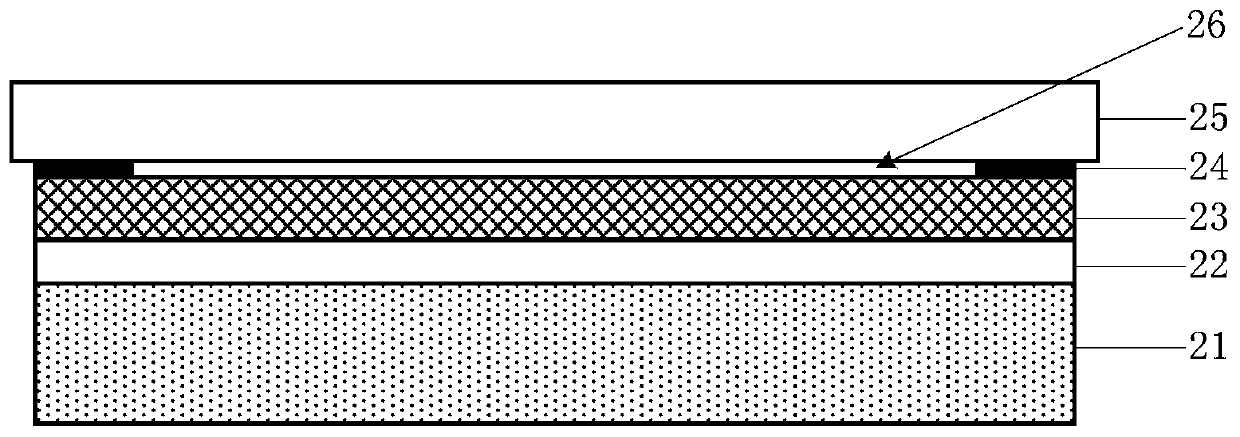
[0016] See figure 2 , A schematic diagram of the layered structure of an embodiment of the touch display device of the present invention. In this embodiment, the touch display device includes: a display panel 21, a touch panel 23, and a cover 25; a full adhesive layer is p...


PUM


Abstract

The invention discloses a touch display device and a manufacturing method thereof. In a panel laminating process, ae display panel and a touch panel are attached through the liquid optical cement by adopting a full-attaching technology, a cover plate and the touch panel are attached through the solid optical cement by adopting a frame attaching technology to form the vacuum cavity. The cover plate, the touch panel and the display panel in the formed touch display device are tightly attached, and optical cement materials are effectively saved.

Description

Technical field [0001] The present invention relates to the field of display technology, and in particular to a touch display device and a manufacturing method thereof. Background technique [0002] Touch Panel (TP), also known as touch screen or touch screen, is a device that is formed on the display surface of an image display device and uses conductors such as a human body or a capacitive pen to input instructions. It can replace a mouse, keyboard, etc. Input devices such as external input devices and mechanical input keys can effectively simplify the structure of electronic products such as computers, mobile phones, electronic meters, and game equipment, and have very broad application prospects. In terms of technical principles, touch panels are mainly capacitive, resistive, ultrasonic, and infrared. [0003] Infrared touch technology currently occupies a large part of the touch market with its accurate touch accuracy and relatively low cost advantages. However, infrared tou...

Claims


Application Information

Patent Timeline
Patent Type & Authority Applications(China)
IPC IPC(8): G06F3/041
CPCG06F3/0412G06F2203/04103G06F3/041B32B37/12B32B37/0015B32B37/144B32B2457/20B32B7/12B32B2457/206B32B2457/202B32B2250/44B32B2457/208B32B7/14B32B17/06B32B37/1207B32B37/1292B32B2037/1215B32B2037/1253B32B2309/68B32B2310/08
Inventor 周明军石振华
Owner SHENZHEN CHINA STAR OPTOELECTRONICS SEMICON DISPLAY TECH CO LTD
Learn More