Method, device, equipment and system for determining focus point, and information processing method

A focus and object technology, applied in the field of information processing, can solve problems such as restricted application scenarios, user inconvenience, user constraints and restrictions

Pending Publication Date: 2020-02-28
BEIJING SAMSUNG TELECOM R&D CENT +1
View PDF24 Cites 14 Cited by
  • Summary
  • Abstract
  • Description
  • Claims
  • Application Information

AI Technical Summary

Problems solved by technology

Although this solution can achieve high accuracy, it will cause constraints and restrictions on the user due to the need for the user to wear additional equipment, which will cause inconvenience to the user and greatly limit the application scenarios of the solution.
For serv...

Method used


Image

  • Method, device, equipment and system for determining focus point, and information processing method
  • Method, device, equipment and system for determining focus point, and information processing method
  • Method, device, equipment and system for determining focus point, and information processing method

Examples


example 1

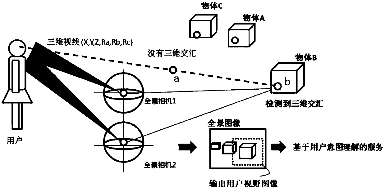
[0408] In this example, the image 3 Two panoramic cameras connected up and down as shown in , obtain two panoramic images, and obtain the user's gaze point based on the two panoramic images as an example. Figure 48 A schematic flowchart of this example is shown in , as shown in the figure, the method of this example may mainly include the following steps:

[0409] Step S1.1: Panoramic camera calibration and panoramic stereo video pair correction

[0410] It can be seen from the foregoing description that when images / videos are captured by a panoramic camera, the panoramic camera needs to be calibrated, and the calibration includes the calibration of each panoramic camera itself and the calibration between two panoramic cameras. After the panoramic camera calibration is completed, the upper and lower panoramic cameras can respectively shoot two sets of panoramic videos of the scene where the user is located, and the two sets of panoramic videos form a panoramic stereoscopi...

example 2

[0423] In this example, the Image 6 As shown in , a panoramic camera is used to obtain two panoramic images, and the user's gaze point is obtained based on the two panoramic images as an example. Figure 49 A schematic flowchart of this example is shown in , as shown in the figure, the method of this example may mainly include the following steps:

[0424] Step S2.1: Camera self-motion acquisition, panoramic image capture at the reference moment, panoramic image capture at the current moment

[0425] In this step, two panoramic images are obtained by controlling the movement of one panoramic camera. For a detailed description of this step, refer to the description of obtaining two panoramic images by one panoramic camera above. Among them, camera self-motion acquisition refers to obtaining self-motion information of the panoramic camera, and obtaining two panoramic images at different times and shooting positions greater than a set distance threshold by controlling the camer...

example 3

[0434] In this example, the Figure 8a or Figure 8b or Figure 8c The non-panoramic camera shown in acquires two panoramic images, and the user's gaze point is obtained based on the two panoramic images as an example. Figure 50 A schematic flowchart of this example is shown in , as shown in the figure, the method of this example may mainly include the following steps:

[0435] Step S3.1: Camera motion control and camera 3D position acquisition

[0436] Due to the limited field of view of the non-panoramic camera, the camera cannot observe all the objects and users in the scene at the same time. Therefore, it is necessary to scan the surrounding environment by controlling the movement of the camera to observe the objects and users in the scene. Camera motion control includes acquiring images of different scene regions by controlling camera rotation and capturing images with stereo disparity by controlling camera translation.

[0437] When controlling the camera movement, ...


PUM


Abstract

The embodiment of the invention provides a method, a device, equipment and a system for determining a focus point, and an information processing method, and belongs to the technical field of information processing. The method for determining the focus comprises the following steps: acquiring at least two images of a scene; and determining a focus point of the object in the image in the scene basedon the at least two images. According to the method provided by the embodiment of the invention, the attention point of the object in the real scene can be determined without wearing any equipment bythe object, the method can be suitable for an actual application scene without wearing extra equipment by the object, and a more natural interaction mode can be provided for the object.

Description

technical field [0001] The present application relates to the technical field of information processing, and specifically, the present invention relates to a method, device, equipment, system and information processing method for determining a focus point. Background technique [0002] The gaze point of the user reflects the object the user gazes at, and by knowing the gaze point of the user, the object of interest can be known. Most of the existing gaze point detection solutions require the user to wear a device equipped with an eye camera for observing the user's eyes and an external camera for observing the user's surrounding environment. Environmental object images to extract the user's gaze point. Although this solution can obtain higher precision, it will impose constraints and restrictions on the user due to the need for the user to wear additional equipment, which will cause inconvenience to the user and greatly limit the application scenarios of the solution. For ...

Claims


Application Information

Patent Timeline
IPC IPC(8): G06T7/20G06T7/80
CPCG06T7/20G06T7/80
Inventor 李炜明张辉王强考月英
Owner BEIJING SAMSUNG TELECOM R&D CENT
Why Eureka
Try Eureka