Circuit for solving problem of power-on jitter of MCU IO level signal and electronic payment self-service equipment

A technology of level signal and self-service equipment, which is applied in the direction of coin starting mechanism, record information storage, data switching current source, etc., can solve the problem of unstable IO level, avoid IO level jitter, improve product competitiveness, The effect of reducing product power consumption

Active Publication Date: 2020-02-28
广东星云开物科技股份有限公司
View PDF9 Cites 2 Cited by
  • Summary
  • Abstract
  • Description
  • Claims
  • Application Information

AI Technical Summary

Problems solved by technology

[0005] The main purpose of the present invention is to solve the problem of false triggering and upper points caused by u

Method used


Image

  • Circuit for solving problem of power-on jitter of MCU IO level signal and electronic payment self-service equipment
  • Circuit for solving problem of power-on jitter of MCU IO level signal and electronic payment self-service equipment
  • Circuit for solving problem of power-on jitter of MCU IO level signal and electronic payment self-service equipment

Examples


Embodiment 1

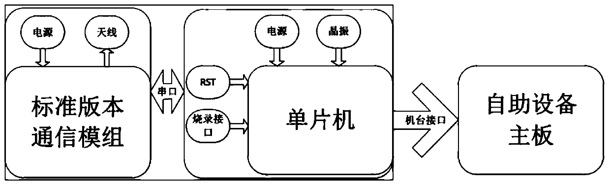
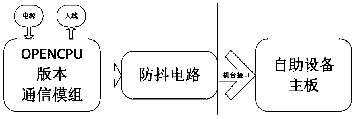
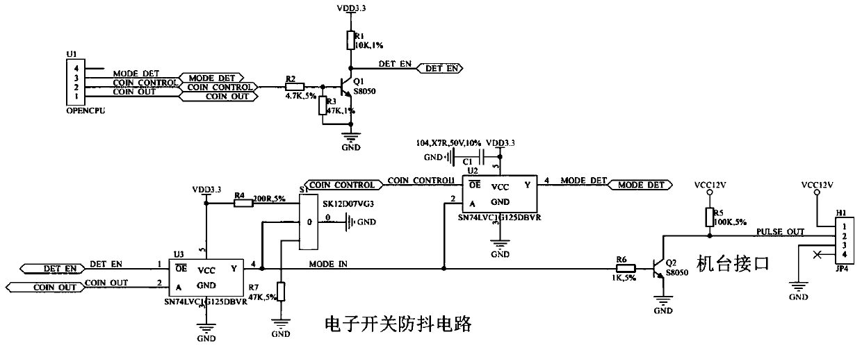
[0026] Embodiment 1 of the present invention proposes a circuit for solving MCU IO level signal power-on jitter, including a communication module and an electronic switch anti-shake circuit, and the communication module is connected to the electronic switch anti-shake circuit. It is characterized in that the communication module includes Communication module U1, resistor R1, resistor R2, resistor R3 and transistor Q1, the COIN_CONTROL of U1 is connected to the first terminal of R2, the second terminal of R2 is respectively connected to the first terminal of R3 and the base of Q1, the emitter of Q1 and the second terminal of R3 are grounded, The collector of Q1 is connected to the first terminal of R1 and the DET_EN terminal respectively, and the second terminal of R1 is connected to the power supply terminal VDD;

[0027] The electronic switch anti-shake circuit includes electronic switch chips U2, U3, resistors R4, R5, R6, R7, capacitor C1, transistor Q2, and toggle switch S1,...

Embodiment 2

[0035] Embodiment 2 of the present invention proposes an electronic payment self-service device, including the above-mentioned MCU IO level signal power-on dithering circuit and the self-service device main board, wherein the electronic switch anti-shake circuit and the self-service device main board are connected through a machine interface.


PUM


Abstract

The invention discloses a circuit for solving a problem of power-on jitter of an MCU IO level signal, and the circuit comprises a communication module and an electronic switch anti-jitter circuit, wherein the communication module is connected with the electronic switch anti-jitter circuit. The electronic switch anti-jitter circuit is arranged to be connected with an OPENCPU version communication module, so IO level jitter during startup is avoided, and the technical problem that the self-service equipment triggers upward score by mistake is solved. The embodiment of the invention further provides the electronic payment self-service equipment. According to the embodiment of the invention, the communication module does not need to be externally connected with an external processor, the structure is simple and the cost is low, and the market competitiveness is good.

Description

technical field [0001] The invention relates to a communication power supply circuit, in particular to a circuit for solving MCU start-up signal level jitter. Background technique [0002] With the rapid development of Internet technology, electronic payment technology has become more and more popular, and self-service equipment as electronic payment terminals has gradually entered people's lives. Existing electronic payment self-service equipment judges the amount paid by the user according to the number of pulses received. The self-service equipment adopts code scanning or coin insertion for payment. After the payment is successful, the payment box will output a low-level pulse or a high-level pulse to the main board of the self-service equipment. The self-service equipment judges the amount paid by the user according to the number of received pulses. [0003] Such as figure 1 As shown, the hardware of the traditional payment box adopts the single-chip microcomputer + co...

Claims


Application Information

Patent Timeline
IPC IPC(8): G07F5/00G07F7/00H04L12/10
CPCG07F5/00G07F7/00H04L12/10
Inventor 杨凯然刘天雄
Owner 广东星云开物科技股份有限公司
Why Eureka
Try Eureka