Transformer core manufacturing device

A transformer core and manufacturing device technology, applied in the direction of inductance/transformer/magnet manufacturing, transportation and packaging, conveyor objects, etc., can solve the problems of low manual production efficiency, improve production efficiency, increase speed and accuracy, The effect of reducing labor intensity

Active Publication Date: 2020-02-28
HXXN ELECTRICITY
View PDF6 Cites 2 Cited by
  • Summary
  • Abstract
  • Description
  • Claims
  • Application Information

AI Technical Summary

Problems solved by technology

[0003] The main purpose of the present invention is to provide a transformer iron core production device

Method used


Image

  • Transformer core manufacturing device
  • Transformer core manufacturing device
  • Transformer core manufacturing device

Examples


Example Embodiment

[0030] The technical solutions in the embodiments of the present invention will be clearly and completely described below in conjunction with the accompanying drawings in the embodiments of the present invention. Obviously, the described embodiments are only a part of the embodiments of the present invention, rather than all the embodiments. Based on the embodiments of the present invention, all other embodiments obtained by those of ordinary skill in the art without creative work shall fall within the protection scope of the present invention.

[0031] It should be noted that all the directional indications (such as up, down, left, right, front, back...) in the embodiments of the present invention are only used to explain the difference between components in a specific posture (as shown in the accompanying drawings). If the relative positional relationship, movement situation, etc. change, the directional indication will change accordingly.

[0032] In addition, in the present inv...


PUM


Abstract

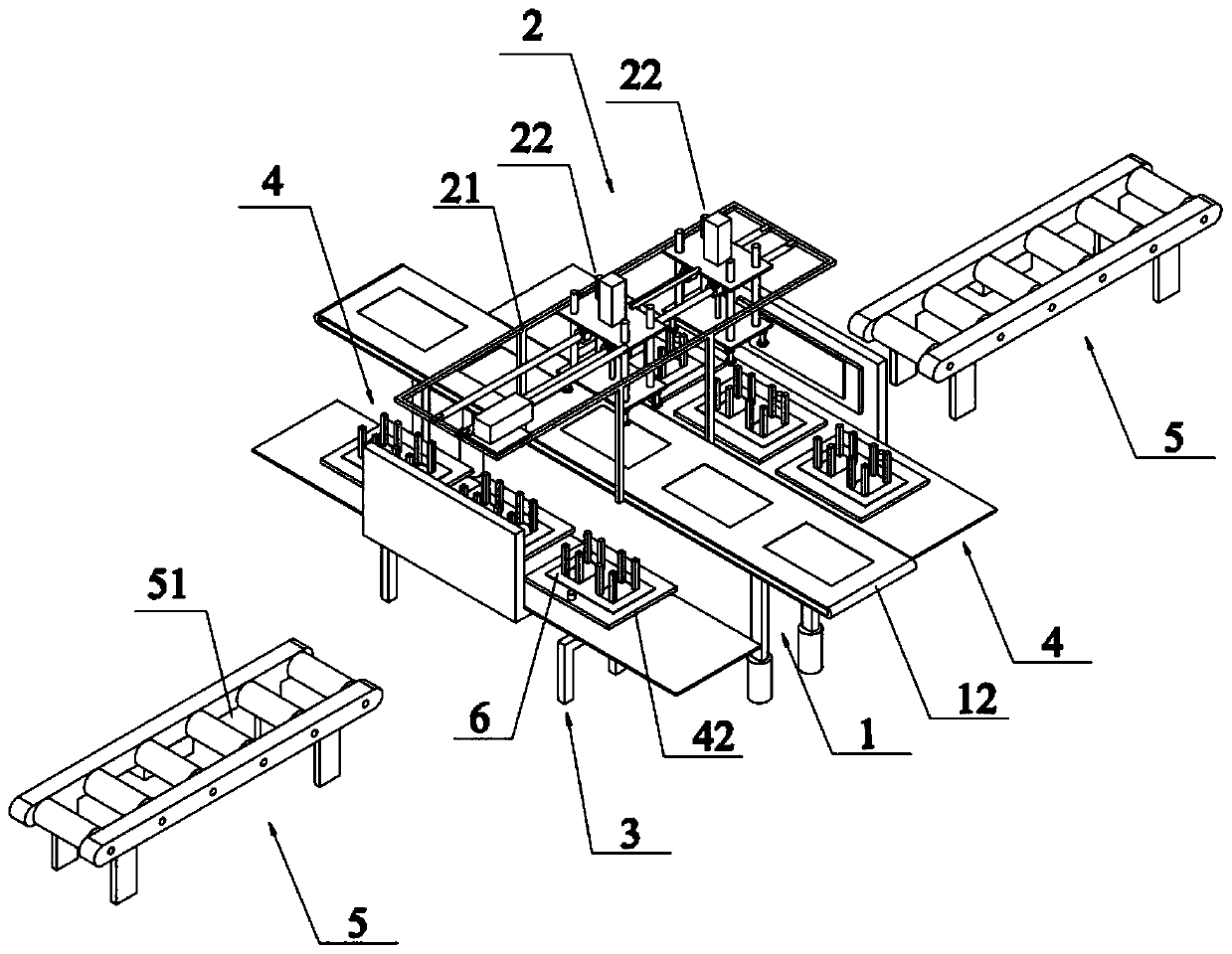
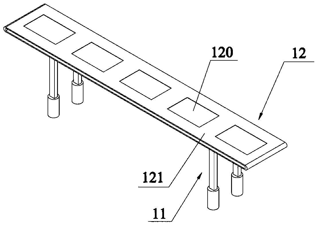
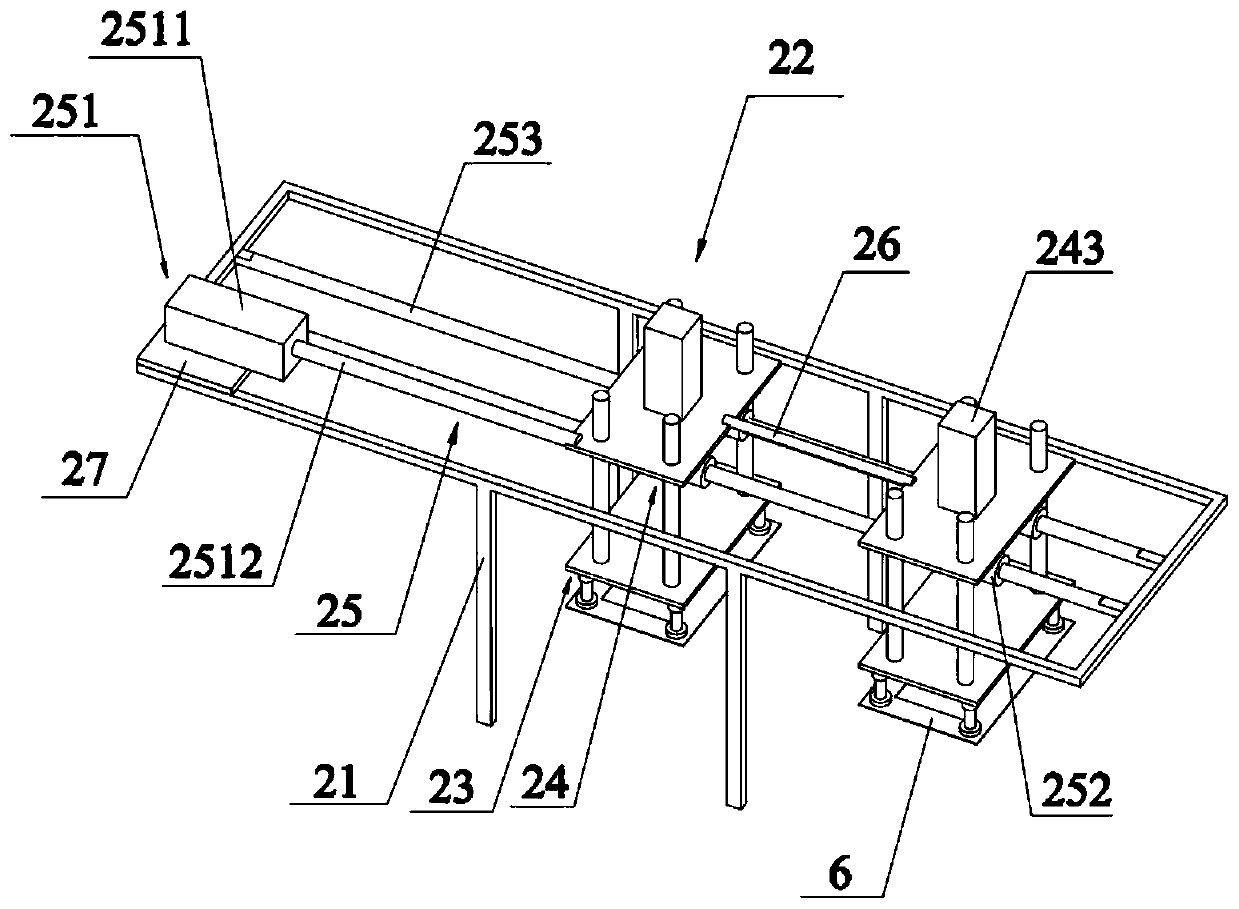
The invention discloses a transformer core manufacturing device, which comprises a loading component, a stacking component disposed above the loading component, a turning table disposed below the stacking component and located on one side of the loading component, a core solidifying component, and a unloading component. The loading component includes a loading base and a belt conveyor. The bottomof the loading base supports the ground. The belt conveyor is disposed on the top of the loading base. The belt conveyor is configured to transport a core to below the stacking component. The stackingcomponent includes a bracket connected to the loading base and located above the belt conveyor and a stacking mechanical arm movably connected to the bracket. The core solidifying component includesa bottom plate connected to the turning table and a stopping frame vertically connected to the bottom plate. The stopping frame can be adjusted in size in order to pass through the inner hole of the core. The stacking mechanical arm is configured to successively stack, press and solidify the core along the stopping frame. The turning table can rotate 90 degrees to make the stopping frame horizontally dock with the transport track of the unloading component. The transformer core manufacturing device realizes the automatic production of the transformer cores and improves production efficiency.

Description

technical field [0001] The invention relates to the field of iron core processing devices, in particular to a transformer iron core manufacturing device. Background technique [0002] The iron core is the main magnetic circuit part of the transformer. It is usually made of stacked hot-rolled or cold-rolled silicon steel sheets with high silicon content and coated with insulating paint. The iron core and the coil wound on it form a complete electromagnetic induction system. In the existing transformer production line, the production of the iron core is usually done manually, but a large number of iron chips need to be stacked during the production process of the iron core. Adjustment, after each stack, check to ensure repeatability and grading accuracy at different widths to ensure that it meets the accuracy requirements. The manual production method is inefficient and labor intensive. Contents of the invention [0003] The main purpose of the present invention is to pr...

Claims


Application Information

Patent Timeline
IPC IPC(8): H01F41/02B65G47/90B65G47/248B65G47/52
CPCB65G47/248B65G47/52B65G47/901H01F41/0233
Inventor 潘建华黄辉龙素超王蕾曹洪浩蔡建国
Owner HXXN ELECTRICITY
Why Eureka
Try Eureka