Supercharge Your Innovation With Domain-Expert AI Agents!

Special tool for power transmission line stay wire back bending

A technology of transmission lines and special tools, which is applied in the direction of overhead lines/cable equipment, etc., can solve problems such as wrist or other parts of the body, time-consuming and laborious bending process, and affect the safe operation of equipment, so as to achieve strong versatility and improve safety , light weight effect

Inactive Publication Date: 2020-02-28
STATE GRID SHANDONG ELECTRIC POWER CO HAIYANG POWER SUPPLY CO +1
View PDF7 Cites 0 Cited by
  • Summary
  • Abstract
  • Description
  • Claims
  • Application Information

AI Technical Summary

Problems solved by technology

[0003] 1. Due to the high hardness and rigidity of the steel strand material, the manual bending process is time-consuming and labor-intensive, and may hurt the operator's wrist or other parts of the body;
[0004] 2. If the back bending process does not meet the standards, there will be a gap between the back bending structure and the wedge-shaped core, and the long-term operation will be affected by the wind vibration, which will cause the end structure of the cable to loosen and cause a safety accident;
[0005] 3. If the cross-section of the steel strand is large, it is more difficult or even difficult to bend back manually. At this time, the operator will use pliers or other tools to bend back, which will damage the galvanized layer on the surface of the steel strand and cause long-term operation. During the process, it is eroded by natural environments such as wind, frost, rain and snow, which is easy to rust, shortens the service life, and affects the safe operation of the equipment.

Method used


Image

  • Special tool for power transmission line stay wire back bending
  • Special tool for power transmission line stay wire back bending
  • Special tool for power transmission line stay wire back bending

Examples


Embodiment Construction

[0028] The following will clearly and completely describe the technical solutions in the embodiments of the present invention with reference to the accompanying drawings in the embodiments of the present invention. Obviously, the described embodiments are only some, not all, embodiments of the present invention. Based on the embodiments of the present invention, all other embodiments obtained by persons of ordinary skill in the art without making creative efforts belong to the protection scope of the present invention.

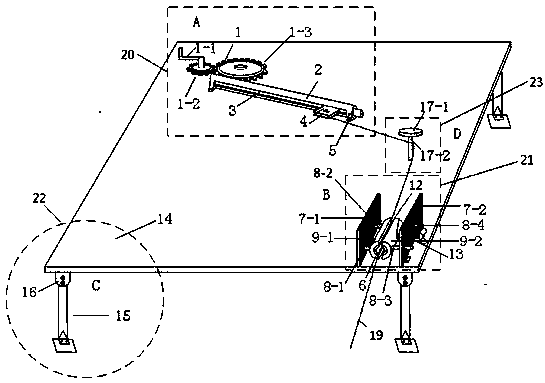
[0029] see Figure 1-3 , including it mainly includes four parts: the short-end driving part A20, the long-end fixing part B21, the support part C22, and the back-bending pillar D23.

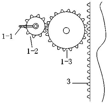
[0030] The short-end transmission part A20 is composed of a gear transmission mechanism 1 , a linear bearing sleeve 2 , a cylindrical rack 3 and a short-end arc groove 4 . Gear transmission mechanism 1 is made up of rocking bar 1-1, driving gear 1-2, driven gear 1-3. The rotat...


PUM

PropertyMeasurementUnit
Diameteraaaaaaaaaa
Diameteraaaaaaaaaa

Abstract

The invention relates to a special tool for power transmission line stay wire back bending. The special tool is widely applied to stay wire installation operation in a process of newly building, reconstructing or repairing an overhead power transmission line of a power system power transmission line, and belongs to the technical field of the special tool for power transmission line electric stay wire back bending. The tool comprises a short-end transmission portion A used for fixing a short end of a steel strand and pulling the steel strand to move, a long-end fixing portion B used for fixinga long end of the steel strand, and a back-bending portion D located between the short-end transmission portion A and the long-end fixing portion B. The short end of the steel strand is fixed on the short end transmission portion A after anticlockwise winding around the back-bending portion D for a circle, and the short end transmission portion A, the long end fixing portion B and the back-bendingportion D are all installed on a support portion C. The tool is simple in structure, convenient to carry and easy and convenient to operate, labor intensity is reduced, efficiency is improved, a technological level is increased, and safety is improved.

Description

technical field [0001] The invention relates to a special tool for the backbending of the stay wire of the transmission line, which is widely used in the installation operation of the stay wire in the new construction, reconstruction or emergency repair of the transmission line of the power system, and belongs to the technical field of the special tool for the backbending of the power stay wire of the transmission line. Background technique [0002] During the installation of transmission line equipment, it is often necessary to use steel strand cables. The two ends of the steel strand stay wires need to be bent back and fixed by wedge-shaped clamps. At present, the backbending structures of the steel strands are mostly made manually on site by operators. There are following deficiencies in the method of making the backbending structure by hand: [0003] 1. Due to the high hardness and rigidity of the steel strand material, the manual bending process is time-consuming and ...

Claims


Application Information

Patent Timeline
IPC IPC(8): H02G1/02B21F1/00
CPCB21F1/00H02G1/02
Inventor 徐晓光朱辰星李山战红羽范荣李豪刘祖超王旭李孟春于成涛郭胜田李之远孙兆键其他发明人请求不公开姓名
Owner STATE GRID SHANDONG ELECTRIC POWER CO HAIYANG POWER SUPPLY CO
Features
  • R&D
  • Intellectual Property
  • Life Sciences
  • Materials
  • Tech Scout
  • Unparalleled Data Quality
  • Higher Quality Content
  • 60% Fewer Hallucinations
Learn More