Power cabinet monitoring and control system and method based on Internet of Things

A technology for power cabinets and control systems, applied in power network operating system integration, transmission systems, information technology support systems, etc. Property safety, preventing theft of electricity, and realizing the effect of unified management

Inactive Publication Date: 2020-02-28
LIAONING TECHNICAL UNIVERSITY
View PDF12 Cites 7 Cited by
  • Summary
  • Abstract
  • Description
  • Claims
  • Application Information

AI Technical Summary

Problems solved by technology

[0002] The traditional power supply mode is one meter per household. Stealing and stealing electricity occur from time to time. The leakage of the power supply system around the meter box in rainy and snowy weather seriously affects the lives of the people.
Countless power losses are caused by illegal power theft every year, and power grid lines are prone to paralysis during the power theft process, which requires power supply companies to spend huge sums of money on maintenance, bringing serious economic burdens to power supply companies
[0003] The above problems are all due to the fact that the door locks of the power cabinet or meter box are easy to open. There is no perfect door lock management system, and there is no interconnection through the Internet of Things.

Method used


Image

  • Power cabinet monitoring and control system and method based on Internet of Things
  • Power cabinet monitoring and control system and method based on Internet of Things

Examples


Embodiment Construction

[0021] The specific implementation manners of the present invention will be further described in detail below in conjunction with the accompanying drawings and embodiments. The following examples are used to illustrate the present invention, but are not intended to limit the scope of the present invention.

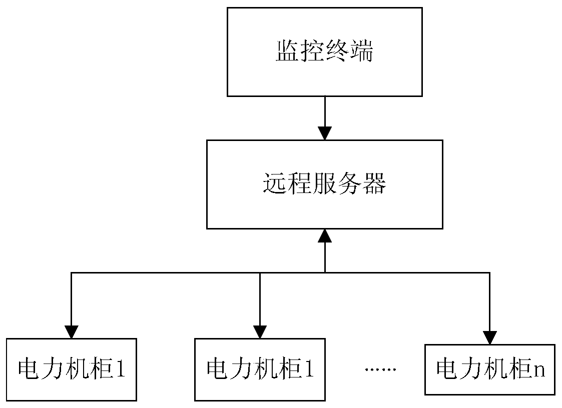
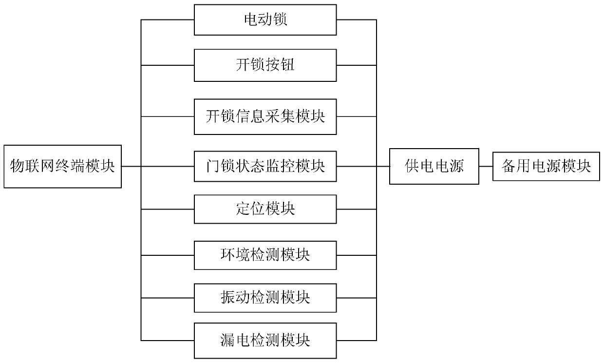
[0022] In this embodiment, a power cabinet monitoring and control system based on the Internet of Things, such as figure 1 As shown, it includes multiple power cabinets, remote servers and monitoring terminals; the power cabinets are as follows figure 2 As shown, it includes an electric lock, an unlock button, an unlock information acquisition module, an Internet of Things terminal module, a door lock status monitoring module, and a power supply; the power supply uses the mains in the power cabinet to supply power to each module in the power cabinet; The electric lock is installed on the electric cabinet door, and the unlock button is installed on the outer surface of th...


PUM


Abstract

The invention provides a power cabinet monitoring and control system and method based on the Internet of Things, and relates to the technical field of power cabinet Internet of Things monitoring. Thesystem comprises a plurality of power cabinets, a remote server and a monitoring terminal, each power cabinet comprises an electric lock, an unlocking button, an unlocking information acquisition module, an Internet of Things terminal module, a door lock state monitoring module and a power supply. The information of unlocking personnel is sent to the remote server through the Internet of Things terminal module, and the remote server judges whether the unlocking personnel have unlocking permission or not so as to control the unlocking of the electric lock; an administrator with an unlocking authority realizes remote unlocking of the electric lock through the monitoring terminal, the remote server and the Internet of Things terminal; meanwhile, the system further comprises a door lock statemonitoring module, an environment detection module, a positioning module, a vibration detection module and an electric leakage detection module, the state of the electric lock and the state of the power cabinet are monitored in real time, and monitoring information is fed back to the remote server in real time.

Description

technical field [0001] The present invention relates to the technical field of Internet of Things for power cabinets, in particular to a monitoring and control system and method for power cabinets based on the Internet of Things. Background technique [0002] The traditional power supply mode is one meter per household, electricity theft and stealing behaviors occur from time to time, and the leakage of the power supply system around the meter box in rainy and snowy weather seriously affects the lives of the people. Countless power losses are caused by illegal power theft every year, and power grid lines are prone to paralysis during the power theft process, which requires power supply companies to spend huge sums of money on maintenance, which has brought serious economic burdens to power supply companies. [0003] The above problems are all due to the fact that the door locks of the power cabinets or meter boxes are easy to open, there is no perfect door lock management sy...

Claims


Application Information

Patent Timeline
Patent Type & Authority Applications(China)
IPC IPC(8): H04L29/08G07C9/00H02J9/06H02J13/00
CPCH04L67/12G07C9/00309G07C9/00571H02J9/061Y04S20/12Y04S20/248Y02B70/30Y02B90/20
Inventor 田立勇于宁
Owner LIAONING TECHNICAL UNIVERSITY
Why Eureka
Try Eureka