Conveying belt edge glue adhesion system

A conveyor belt and side glue technology, applied in the direction of mixers, transportation and packaging, mixers with rotating stirring devices, etc., can solve the problems that the glue cannot be recycled, the conveyor belt cannot be bonded, and it does not conform to the interests of the enterprise, etc., to achieve The effect of meeting the need for reuse, avoiding waste, and saving production costs

Active Publication Date: 2020-03-03
HENAN TIANGONG RUBBER TECHNOLOGY CO LTD
View PDF12 Cites 0 Cited by
  • Summary
  • Abstract
  • Description
  • Claims
  • Application Information

AI Technical Summary

Problems solved by technology

[0002] Conveyor belts are generally classified according to whether there are traction parts: conveyor belt equipment with traction parts and conveyor belt equipment without traction parts; there are many types of conveyor belt equipment with traction parts, mainly: belt conveyor, plate conveyor, Trolley conveyors, escalators, moving walks, scraper conveyors, buried scraper conveyors, bucket conveyors, bucket elevators, suspension conveyors and overhead ropeways, etc.; conveyor belt equipment without traction parts are common Rollers rotate, screw conveyors, etc. The conveyor belt needs to be bonded during processing, but it is impossible to bond conveyor belts of different thicknesses in the prior art, and it is necessary to bond conveyor belts of different thicknesses. Use the corresponding bonding device, and the glue in the bonding process cannot be recycled, which increases the production cost and does not conform to the interests of the enterprise itself

Method used


Image

  • Conveying belt edge glue adhesion system
  • Conveying belt edge glue adhesion system
  • Conveying belt edge glue adhesion system

Examples


Embodiment Construction

[0018] The following will clearly and completely describe the technical solutions in the embodiments of the present invention with reference to the accompanying drawings in the embodiments of the present invention. Obviously, the described embodiments are only some, not all, embodiments of the present invention. Based on the embodiments of the present invention, all other embodiments obtained by persons of ordinary skill in the art without making creative efforts belong to the protection scope of the present invention.

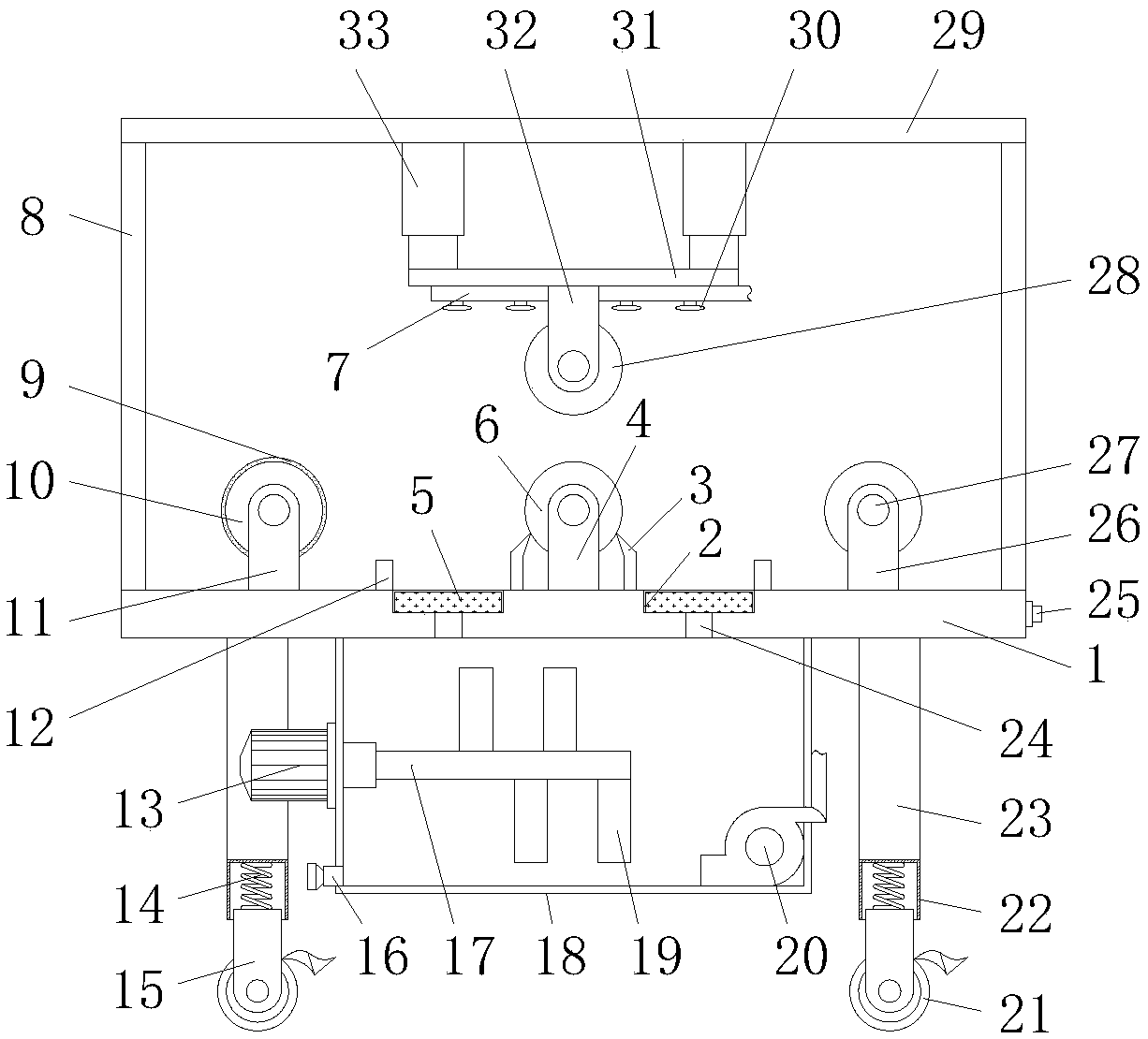
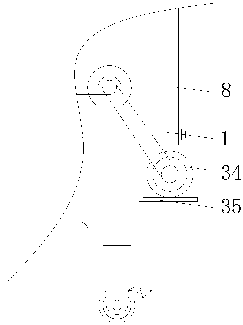
[0019] see Figure 1-3 , a conveyor belt edge glue bonding system, comprising a support base 1, a fixed leg 23 is fixedly connected around the bottom of the support base 1, and a sleeve 22 is fixedly connected to the bottom of the fixed leg 23, and the top end of the inner cavity of the sleeve 22 The movable legs 15 are movably connected by the spring 14, and the bottom of the movable legs 15 is movably equipped with a walking wheel 21, the middle end of the b...


PUM


Abstract

The invention discloses a conveying belt edge glue adhesion system, which comprises a supporting seat, wherein the middle end of the bottom of the supporting seat is fixedly connected with a glue storage box, a stirring motor is fixedly installed at the middle end of the left side of the glue storage box, the output shaft of the stirring motor is fixedly connected with a stirring shaft, stirring blades are fixedly connected to the outer surface of the stirring shaft, a pump machine is fixedly installed at the right end of the bottom of the inner cavity of the glue storage box, and the outlet of the pump machine is movably connected with a spray head through a pipeline. According to the invention, through the effects of the first supporting plate, the electric telescopic rod, the second supporting plate, the upper extrusion roller bracket and the upper extrusion roller, the adhesion requirements of people on conveying belts with different thicknesses can be met so as to provide great convenience in use by people; and through the effects of the scraping plate, the first reserved groove, the baffle, the filtering screen and the second reserved groove, the requirements on repeated utilization of a glue can be met so as to avoid the waste of the glue, save the production cost and meet the benefits of enterprises.

Description

technical field [0001] The invention relates to the technical field of conveyor belts, in particular to a conveyor belt edge glue bonding system. Background technique [0002] Conveyor belts are generally classified according to whether there are traction parts: conveyor belt equipment with traction parts and conveyor belt equipment without traction parts; there are many types of conveyor belt equipment with traction parts, mainly: belt conveyors, slat conveyors, Trolley conveyors, escalators, moving walks, scraper conveyors, buried scraper conveyors, bucket conveyors, bucket elevators, suspension conveyors and overhead ropeways, etc.; conveyor belt equipment without traction parts are common Rollers rotate, screw conveyors, etc. The conveyor belt needs to be bonded during the processing, but it is impossible to bond conveyor belts of different thicknesses in the prior art, and it is necessary to bond conveyor belts of different thicknesses. Use the corresponding bonding de...

Claims


Application Information

Patent Timeline
Patent Type & Authority Applications(China)
IPC IPC(8): B32B37/10B32B37/12B01F7/04
CPCB32B37/10B32B37/1284B32B2433/02B01F27/1125B01F27/191B01F27/70
Inventor 汤占鹏姚红卫杨宁刘天哲
Owner HENAN TIANGONG RUBBER TECHNOLOGY CO LTD
Why Eureka
Try Eureka