Automatic rod sticking and dispensing route and dispensing method

A dispensing and sticking technology, which is applied to coatings, devices for coating liquid on surfaces, special surfaces, etc., can solve problems such as unreasonable dispensing track design, unstable bonding quality, and high production costs, and achieve Optimize the dispensing track route, high dispensing efficiency and good consistency

Pending Publication Date: 2020-03-31
天津市环智新能源技术有限公司
View PDF0 Cites 0 Cited by
  • Summary
  • Abstract
  • Description
  • Claims
  • Application Information

AI Technical Summary

Problems solved by technology

[0003] The invention provides an automatic sticking stick dispensing route and dispensing method, which is suitable for the bonding of whole silicon rods or spliced ​​silicon rods of various sizes and specifications, and solves the problem of dispensing track during automatic bonding in the prior art. The technical problems of unstable bonding quality, low strength and high production cost caused by unreasonable route design

Method used


Image

  • Automatic rod sticking and dispensing route and dispensing method
  • Automatic rod sticking and dispensing route and dispensing method
  • Automatic rod sticking and dispensing route and dispensing method

Examples


Embodiment 1

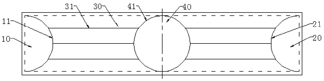
[0059] Such as figure 1 As shown, the shape of the dispensing route of the first dispensing area 10 is a semicircular curve 11, and the dispensing needle starts from the upper end point on the left side of the material seat 50, that is, the first dispensing area 10 is close to the upper end of the material seat 50. At the end point, rotate the dispensing clockwise until the lower end point ends, and then lift the dispensing needle.

[0060] After finishing the dispensing route of the first glue dispensing area 10, begin to dispensing glue to the dispensing straight line 31 of the third glue dispensing area 30 on the left side, and then to the lower section straight line 31 in the third glue dispensing area 30 on the left side , Middle section straight line 31 and upper section straight line 31 carry out glue dispensing. Specifically, the dispensing needle first moves to the intersection of the straight line 31 on the side of the lower section and the curve 11, and moves along...

Embodiment 2

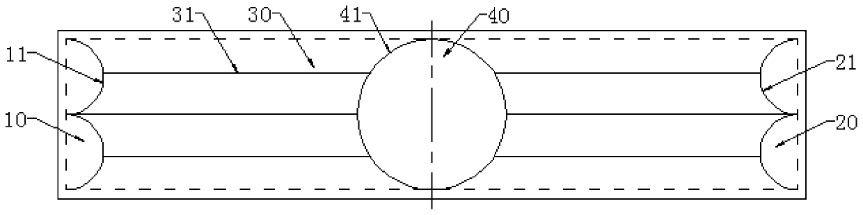
[0065] Such as Figure 5 As shown, the difference from Embodiment 1 is only the difference in the shape of the dispensing route in the third dispensing area 30, the dispensing method of the first dispensing area 10, the second dispensing area 20 and the fourth dispensing area 40 are the same and are omitted here. The third glue dispensing area 30 includes two horizontally parallel straight lines 31 correspondingly arranged on the left and right sides, and symmetrically arranged on both sides of the central axis of the material holder 50 in the width direction.

[0066] After finishing the dispensing route of the first glue dispensing area 10, begin to dispensing glue to the dispensing straight line 31 of the third glue dispensing area 30 on the left side, and then to the lower section straight line 31 in the third glue dispensing area 30 on the left side Carry out dispensing with upper section straight line 31. Specifically, the dispensing needle first moves to the intersect...

Embodiment 3

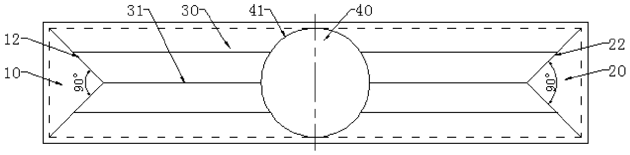
[0069] Such as Figure 4 As shown, the difference from Embodiment 1 is only the difference in the shape of the dispensing route in the third dispensing area 30, the dispensing method of the first dispensing area 10, the second dispensing area 20 and the fourth dispensing area 40 are the same and are omitted here. The third dispensing area 30 includes a horizontal straight line 31 and is located at the central axis of the material holder 50 in the width direction.

[0070] Start dispensing in the third dispensing area 30 on the left, lift the dispensing needle and move to the apex position on the right side of the curve 11, that is, the intersection with the middle axis in the width direction of the material seat 50, and move along a horizontal line from the left Dispensing until the end point on the right side, that is, ending at the apex of the curve 41 on the left side of the fourth dispensing area 40, and then lift the dispensing needle.

[0071] Then the third dispensing...


PUM


Abstract

The invention provides an automatic rod sticking and dispensing route. The dispensing route comprises a first dispensing area, a second dispensing area and a third dispensing area, wherein the first dispensing area and the second dispensing area are respectively arranged at two ends of a material seat, the third dispensing area is arranged between the first dispensing area and the second dispensing area, and the third dispensing area is respectively connected with the first dispensing area and the second dispensing area. The invention further provides an automatic rod sticking and dispensing method. The dispensing route is advantaged in that bonding requirements of surfaces of various monocrystalline silicon rods are met, the dispensing track route is optimized to the maximum extent, the adhesive solution can be evenly distributed on a bonding surface of the silicon rod, the dispensing effect is good, dispensing efficiency is high, consistency is good, no bubble is generated in the dispensing process, continuity is good, the bonding effect good in stability, even in adhesive solution and good in strength can be obtained after the silicon rod is placed, and the activation rate of rod bonding equipment is increased.

Description

technical field [0001] The invention belongs to the technical field of bonding solar-grade monocrystalline silicon rods, and in particular relates to an automatic sticking rod dispensing route and a dispensing method. Background technique [0002] The rod sticking process is mainly to prepare for the subsequent wire cutting process, that is, to bond the monocrystalline silicon square rod to a reusable material holder, and then send it to the wire cutting process for slicing. In the past, the bonding of single crystal silicon rods was mostly done manually, and the glue application route was not uniform. The glue application and water application required experience, and the control of the glue application amount was unstable, which often resulted in post-production problems caused by excessive or small glue application. Unnecessary damage such as chip drop and collapse occurred in the line cutting process, and the waste of glue was serious, and the bonding quality was unstabl...

Claims


Application Information

Patent Timeline
Patent Type & Authority Applications(China)
IPC IPC(8): B05D5/00
CPCB05D5/00
Inventor 李海彬危晨刘晓伟李建弘武治军史丹梅
Owner 天津市环智新能源技术有限公司
Why Eureka
Try Eureka