Method and device for providing a virtual tomographic stroke follow-up examination image

A technology for tomography and follow-up examinations, applied in nuclear methods, medical images, image enhancement, etc., and can solve problems such as noise effects

Pending Publication Date: 2020-03-03
SIEMENS HEALTHCARE GMBH
View PDF10 Cites 2 Cited by
  • Summary
  • Abstract
  • Description
  • Claims
  • Application Information

AI Technical Summary

Problems solved by technology

However, threshold-based methods are susceptible to noise and do not

Method used


Image

  • Method and device for providing a virtual tomographic stroke follow-up examination image
  • Method and device for providing a virtual tomographic stroke follow-up examination image
  • Method and device for providing a virtual tomographic stroke follow-up examination image

Examples


Embodiment Construction

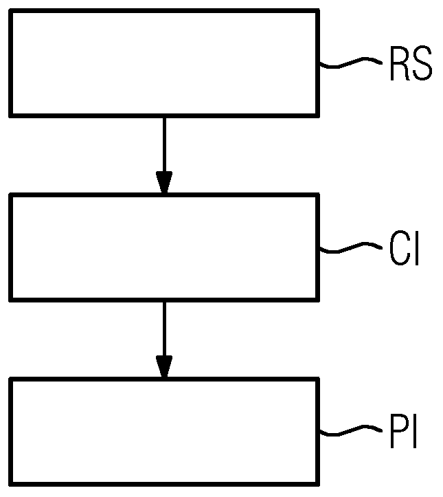
[0090] figure 1 A flowchart of a method for providing a virtual tomographic stroke follow-up image is shown, the method comprising the following steps:

[0091] - receiving a sequence of temporally continuous tomographic perfusion data of the RS examination region,

[0092] - Compute a virtual tomographic stroke follow-up examination image of the CI examination region by applying the trained machine learning algorithm to a sequence of temporally continuous tomographic perfusion imaging datasets, and

[0093] -Provides PI virtual tomography stroke follow-up examination images.

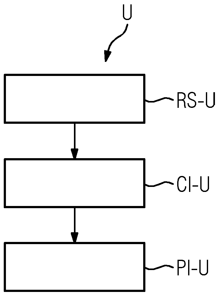
[0094] figure 2 A provision unit U for providing virtual tomographic stroke follow-up examination images is shown, having:

[0095] - a receiving interface RS-U designed to receive a sequence of temporally continuous tomographic perfusion imaging datasets of the RS examination region,

[0096] - a computing unit CI-U designed to compute a virtual tomographic stroke follow-up examination image of th...


PUM


Abstract

A method and a device for providing a virtual tomographic stroke follow-up examination image. The method includes: receiving a sequence of temporally successive tomographic perfusion imaging data setsof a region for examination; calculating the virtual tomographic stroke follow-up examination image of the region for examination by applying a trained machine learning algorithm to the sequence of temporally successive tomographic perfusion imaging data sets received; and providing the virtual tomographic stroke follow-up examination image calculated.

Description

technical field [0001] The present invention relates to a method for providing a virtual tomography stroke follow-up examination image. The invention also relates to a providing unit, a computer program product and a computer readable storage medium. Background technique [0002] Dynamic contrast-enhanced (DCE) imaging or perfusion imaging, also known as computed tomography (CT), DCE-CT, or perfusion CT, is an imaging technique that can be used to analyze physiological properties, especially tissue perfusion. In addition, DCE imaging can help diagnose strokes, in which parts of the brain are starved of oxygen due to poor blood circulation and are irreversibly damaged. [0003] In order to identify damaged areas, an image sequence is acquired during the application of the contrast agent, and the temporal change in the attenuation values ​​is determined for individual pixels or specific areas. Perfusion properties can be calculated based on these curves, which are then usual...

Claims


Application Information

Patent Timeline
IPC IPC(8): G06T7/11G06N3/04G06N3/08G06N20/00G06N20/10
CPCG06T7/11G06N3/08G06N20/10G06N20/00G06T2207/10081G06T2207/20081G06T2207/20084G06T2207/30016G06N3/045G06T7/0016G06T2207/10096G06T2207/10076G06T2207/30104G16H30/20G16H50/20G16H50/30G16H30/40G06N3/047G06N3/044G06T7/0012
Inventor N·凯瑟S·施密特
Owner SIEMENS HEALTHCARE GMBH
Why Eureka
Try Eureka