
Dust removal device of electric automation equipment for easy cleaning

A technology of electrical automation and dust removal device, which is applied in the direction of combination device, chemical instrument and method, and separation of dispersed particles, which can solve secondary pollution, slow down the speed of the first dust collection bucket and the second dust collection bucket, and dismantle the air filter element. Long installation time and other problems, to achieve the effect of reducing labor intensity, improving effect and speeding up

Inactive Publication Date: 2020-03-06
邢二江
View PDF13 Cites 1 Cited by
  • Summary
  • Abstract
  • Description
  • Claims
  • Application Information

AI Technical Summary

Problems solved by technology

[0003] At present, there are still some deficiencies in the existing dust removal device for electrical automation equipment, for example; When the interior is cleared, it will diffuse into the air again to cause secondary pollution, which reduces the effect of the dust removal device, and the existing dust removal device for electrical automation equipment cannot clean the first dust collection bucket and the second dust collection bucket on the dust collection device. Automatic flushing slows down the cleaning speed of the first dust collection bucket and the second dust collection bucket, increases the labor intensity of the operator when cleaning the first dust collection bucket and the second dust collection bucket, and the air filter element on the dust removal device It takes a long time to disassemble and assemble, and you need to use disassembly and assembly tools to disassemble and assemble it, which reduces the convenience of cleaning the air filter on the dust removal device

Method used


Image

  • Dust removal device of electric automation equipment for easy cleaning
  • Dust removal device of electric automation equipment for easy cleaning
  • Dust removal device of electric automation equipment for easy cleaning

Examples


Embodiment Construction

[0027] The following will clearly and completely describe the technical solutions in the embodiments of the present invention with reference to the accompanying drawings in the embodiments of the present invention. Obviously, the described embodiments are only some, not all, embodiments of the present invention.

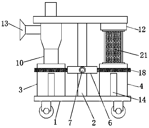
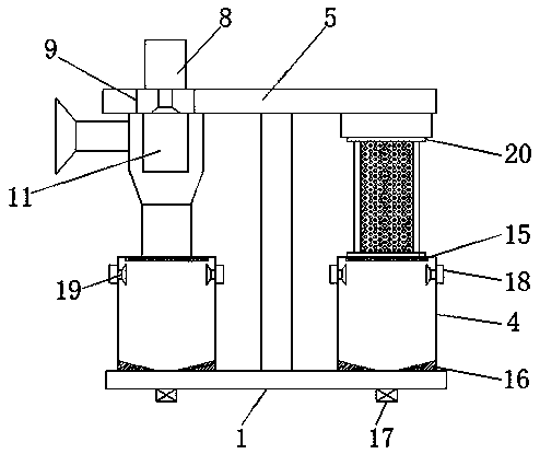
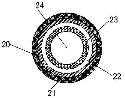
[0028] see Figure 1-Figure 3 , the present invention provides a technical solution: a dust removal device for electrical automation equipment that is easy to clean, including a mobile base 1 on which a support rod 2, a first dust collection bucket 3 and a second dust collection bucket 4 are arranged, so that The support rod 2 is connected to the middle of the upper surface of the mobile base 1 through a rivet, the first dust collection bucket 3 is connected to the left side of the upper surface of the mobile base 1 through a rivet, and the second dust collection bucket 4 is connected to the left side of the upper surface of the mobile base 1 through a rivet. The rig...


PUM


Abstract

The invention discloses a dust removal device of electric automation equipment for easy cleaning. The device comprises a moving base, and a support rod, a first dust collecting can, and a second dustcollecting can are disposed on the moving base. The support rod is connected to the middle of the upper surface of the moving base through a rivet. The first dust collecting can is connected to the left side of the upper surface of the moving base through a rivet. The second dust collecting can is connected to the right side of the upper surface of the moving base through a rivet. The upper end ofthe support rod is provided with a ventilation channel and a connection pipe. The ventilation channel is connected with the upper end of the support rod through a rivet. The connection tube is connected with the middle of the support rod through a rivet. A water pipe joint is disposed on the connection tube. The automatic flushing of the first dust collecting can and the second dust collecting can on the dust removal device can be achieved, thereby speeding up cleaning speed of the first dust collecting can and the second dust collecting can and reducing the labor intensity of an operator during washing the first dust collecting can and the second dust collecting can.

Description

technical field [0001] The invention relates to the technical field of dust removal devices, in particular to a dust removal device for electrical automation equipment that is easy to clean. Background technique [0002] According to patent 201910407894.9, it is known that a dust removal device for electrical automation equipment includes an air inlet pipe, a cyclone dust collector, an air outlet, a dust collection bucket, an air duct, and an air filter element. The inlet end of the cyclone dust collector is connected to the air inlet pipe. The air intake pipe is connected to the dust outlet of the electrical automation equipment, the lower end of the cyclone dust collector is connected to the dust collection bucket, the upper exhaust end of the cyclone dust collector is connected to one end of the air duct, and the air duct The other end is connected with the upper end of the air filter element. [0003] At present, there are still some deficiencies in the existing dust re...

Claims


Application Information

Patent Timeline
IPC IPC(8): B01D50/00
CPCB01D50/10
Inventor 邢二江
Owner 邢二江
Learn More