Damper

A technology of dampers and damping pistons, which is applied in the field of hydraulic dampers, can solve problems such as inconstant damping force, changes in damping force, and influence on damping and buffering effects, and achieve the effect of ensuring damping force and preventing changes

Inactive Publication Date: 2020-03-06
佛山市南海区然铭力佳利五金制品有限公司
View PDF0 Cites 0 Cited by
  • Summary
  • Abstract
  • Description
  • Claims
  • Application Information

AI Technical Summary

Problems solved by technology

Generally, there will be a gap between the damping piston and the cylinder. When the piston rod is compressed and retracted, the damping piston will deviate to one

Method used


Image

  • Damper
  • Damper

Examples


Example Embodiment

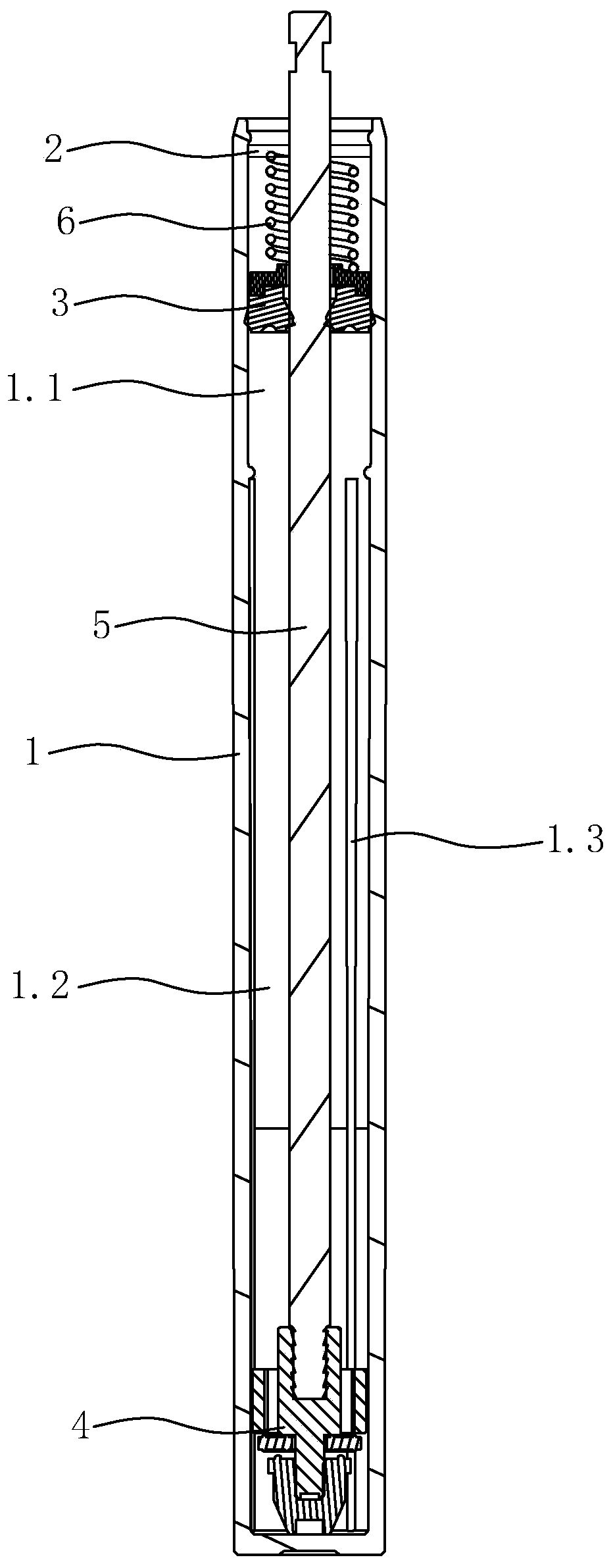
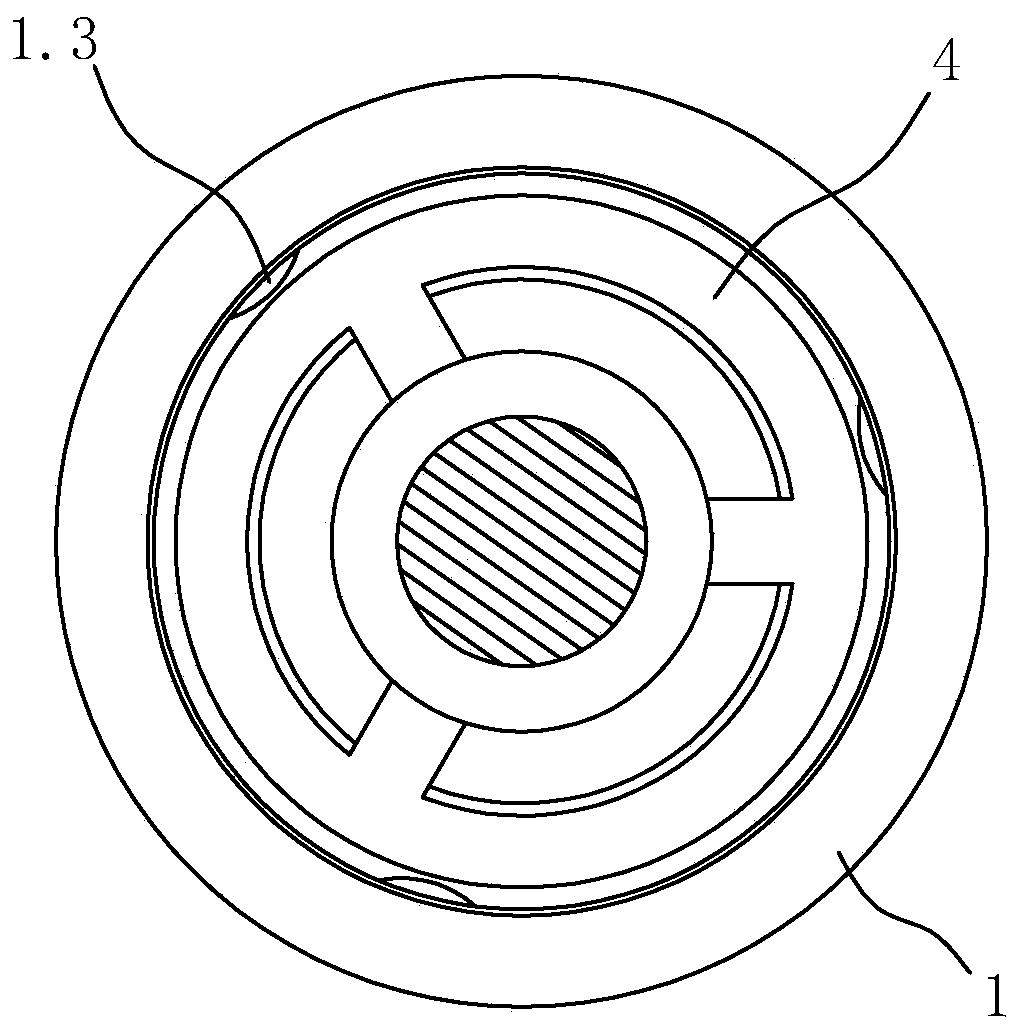
[0009] Such as figure 1 , 2 As shown, a damper includes a cylinder barrel with a reservoir section 1.1 and a hydraulic cylinder section 1.2, a plug cover fixed at the cylinder port of the cylinder barrel 1, a sealing ring plug 3 at the reservoir section 1.1, and The damping piston 4 of the hydraulic cylinder section 1.2, the piston rod 5 that is fixed to the damping piston 4 and that the sealing sliding sleeve passes through the sealing ring plug 3 and out of the plug cover 2, and the spring 6 that keeps the sealing ring plug 3 sliding toward the hydraulic cylinder section 1.2 . In the present invention, the inner peripheral wall of the hydraulic cylinder section 1.2 of the cylinder tube 1 is formed with a plurality of axially extending ribs 1.3.

[0010] The cylinder tube 1 is divided into two sections by the retaining ring 1.3, the inner section is the hydraulic cylinder 1.2, and the outer section is the reservoir 1.1. The sealing ring plug 3 slides in the liquid storage cylin...


PUM


Abstract

The invention discloses a damper. The damper comprises a cylinder barrel which is provided with a liquid storing cylinder section and a hydraulic cylinder section, a plug lid which is fixed to an opening of the cylinder barrel, a sealing ring plug which is arranged on the liquid storing cylinder section, a damping piston which is disposed on the hydraulic cylinder section, a piston rod which is fixed to the damping piston, penetrates through the sealing ring plug in a sealing sliding mode and penetrates out of the plug lid and a spring which keeps the sealing ring plug in a tendency to slidingtowards the hydraulic cylinder section. The damper is characterized in that a plurality of axially-extending protruding ribs which are formed on the inner circumference wall of the hydraulic cylindersection of the cylinder barrel. As the multiple protruding ribs are formed on the inner circumference wall of the hydraulic cylinder section of the cylinder barrel, sliding of the damping piston is limited through the protruding ribs, side friction between the damping piston and the inner wall of the cylinder barrel is prevented, change of the damping degree is prevented, and thus the constant damping degree of the damper is ensured.

Description

technical field [0001] The invention relates to the technical field of hydraulic dampers. Background technique [0002] In the furniture industry, the self-closing device often uses a damper with a long stroke to buffer the self-closing. The damper is mainly composed of a cylinder with a liquid storage cylinder section and a hydraulic cylinder section, a plug cap fixed at the mouth of the cylinder barrel, a sealing ring plug at the liquid storage cylinder section, a damping piston at the hydraulic cylinder section, and a fixed damping piston. And the sealing slides through the piston rod of the sealing ring plug and passes through the plug cover, and the spring that keeps the sealing ring plug sliding towards the hydraulic cylinder section. A retaining ring inside the cylinder is divided into two sections, the inner section is the hydraulic cylinder, and the outer section is the fluid storage cylinder. Generally, there will be a gap between the damping piston and the cylin...

Claims


Application Information

Patent Timeline
IPC IPC(8): F16F9/32F16F9/19
CPCF16F9/19F16F9/3235
Inventor 唐善培
Owner 佛山市南海区然铭力佳利五金制品有限公司
Why Eureka
Try Eureka