
Electric heating drying oven

A technology of electric blast drying and drying oven, which is applied in the direction of drying solid materials, drying chamber/container, drying gas arrangement, etc. It can solve the problems of low heat energy utilization rate, occupying the space of drying oven, small air outlet, etc., and achieves convenience Overhaul inspection and maintenance cleaning, improve the utilization rate of heat energy, and ensure the effect of test accuracy

Inactive Publication Date: 2020-03-06
浙江智城医疗器械有限公司
View PDF0 Cites 1 Cited by
  • Summary
  • Abstract
  • Description
  • Claims
  • Application Information

AI Technical Summary

Problems solved by technology

[0004] The object of the present invention is to provide an electric blast drying box to solve the problems in the above-mentioned background technology, but the blower and the air outlet duct structure of the current electric blast drying box are unreasonable. The blowers are all inside the inner tank or Above the bottom, it is unsightly and takes up the use space of the drying box; the air outlet duct cannot be fully opened, and the air outlet is too small. When it is necessary to perform a gas test on the air outlet of the drying box, it is not convenient to use a test instrument to detect the gas at the air outlet. Moreover, the structure of the currently used drying box is integrally formed, which is inconvenient to overhaul, maintain and clean the drying box. At the same time, the hot air circulation efficiency inside the drying box is low, and the heat energy utilization rate is low, resulting in poor drying effect.

Method used


Image

  • Electric heating drying oven
  • Electric heating drying oven
  • Electric heating drying oven

Examples


Embodiment Construction

[0026] The following will clearly and completely describe the technical solutions in the embodiments of the present invention with reference to the accompanying drawings in the embodiments of the present invention. Obviously, the described embodiments are only some, not all, embodiments of the present invention. Based on the embodiments of the present invention, all other embodiments obtained by persons of ordinary skill in the art without making creative efforts belong to the protection scope of the present invention.

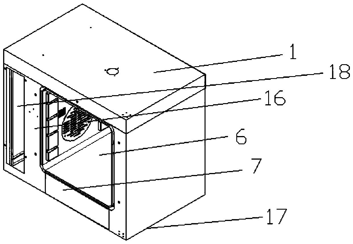
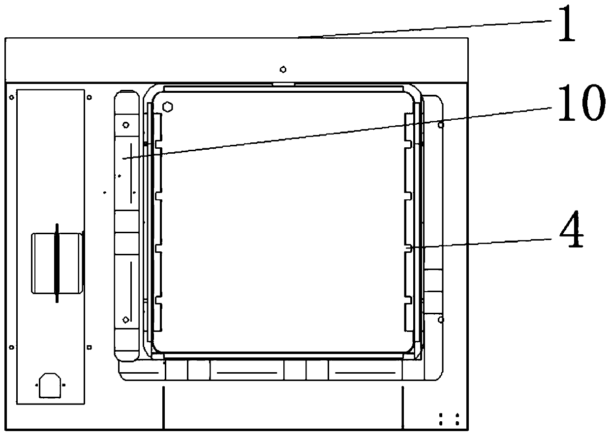
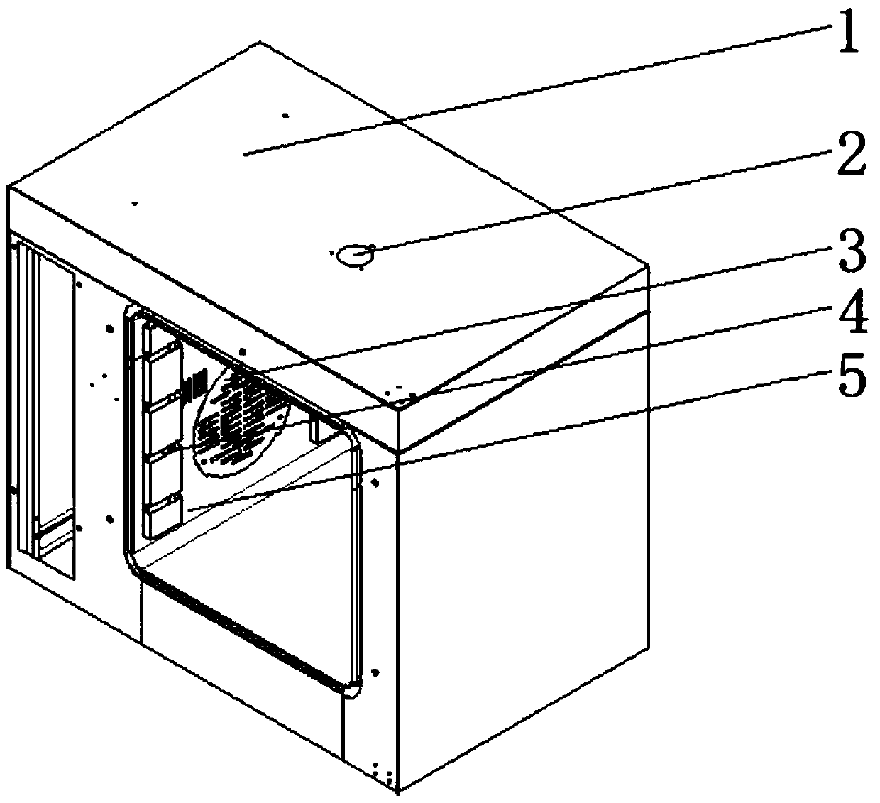
[0027] see Figure 1-5 , the present invention provides a technical solution: an electric blast drying oven, comprising an outer casing 1, a blower fan 3, a heating pipe 4 and an inner tank 5, one side of the inner tank 5 is embedded and fixedly installed with a fan 3, and the fan 3 Heating pipes 4 are fixedly installed on both inner walls and inner bottom ends of the opening of the liner 5 on one side of the inner liner 5, and convex riveting structures 8 are...


PUM


Abstract

The invention discloses an electric heating drying oven. The electric heating drying oven comprises a shell, a fan, heating tubes and a liner. The fan is fixedly embedded into the outer surface of oneside of the liner. The heating tubes are fixedly installed on the outer surfaces and the outer bottom ends of the two sides of an opening in the side, with the fan, of the liner respectively. Protruding rivet structures are fixedly installed on the outer surfaces of the two sides of the liner respectively. Each protruding rivet structure comprises a lifting lug and a blocking piece. The liner ismovably connected with an outer shell. An air outlet pipe is installed in the outer shell and the top of the liner in penetration manner. A tube end connection flange and a tube end installation flange are fixedly installed at the two ends of the air outlet pipe respectively. The tube end connection flange is used for connection with a drying oven air outlet channel. According to the electric heating drying oven, because of a series of arranged structures, the circulation efficiency of hot air inside the drying oven is improved in the process of drying materials because of application of the electric heating drying oven, the use ratio of heat energy is increased, and the better drying effect is achieved.

Description

technical field [0001] The invention belongs to the field of drying technology, and in particular relates to an electric blast drying oven. Background technique [0002] Drying ovens are divided into two categories: electric blast drying ovens and vacuum drying ovens according to the different drying materials. Now they have been widely used in chemical industry, electronic communication, plastics, cables, electroplating, hardware, automobiles, optoelectronics, rubber products, Mold, spraying, printing, medical, aerospace and colleges and universities and other industries. The huge market demand makes the variety of drying ovens diversified, and the structural quality of the products is also different. The electric blast drying oven is a device that uses electric heating to perform blast drying. The existing electric blast drying ovens are generally It includes: a drying box, which has a drying chamber inside; a blower assembly, which includes a blower with an air inlet and...

Claims


Application Information

Patent Timeline
IPC IPC(8): F26B9/06F26B25/00F26B25/06F26B21/00F26B23/06F26B25/12F26B25/10
CPCF26B9/06F26B21/004F26B23/06F26B25/00F26B25/06F26B25/10F26B25/12
Inventor 陶埼波肖健董栩烽
Owner 浙江智城医疗器械有限公司
Learn More