Starting framework and method of Bootloader flashing program for vehicle control unit
A vehicle controller and program technology, which is applied in the field of start-up architecture of the vehicle controller using Bootloader to write programs, can solve problems such as low success rate, power failure, and failure to use normally, and meet the requirements of functionalization and capacity expansion. Effect with low trigger probability
- Summary
- Abstract
- Description
- Claims
- Application Information
AI Technical Summary
Problems solved by technology
Method used
Image
Examples
Embodiment 1
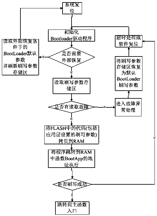
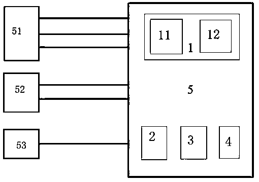
[0069] S1: Vehicle controller 5 resets the system and initializes the Bootloader driver, including initialization of the microcontroller, system clock, external IO, power chip, enabling internal interrupts, bootloader driver flashing program, etc.
[0070] S2: The high effective digital input circuit outputs 3 high effective digital signals to the vehicle controller 5, the low effective digital input circuit outputs 1 low effective digital signal to the vehicle controller 5, and the PWM input circuit outputs 1 fixed frequency and duty cycle The PWM signal of the empty ratio is sent to the vehicle controller 5, and the judging module 4 judges that no external recovery is needed.
[0071] S3: The Bootloader program reads the flashing parameter storage area 11, and obtains related flashing parameters.
[0072] S4: The fault exception processing module 2 judges that there is no read fault.
[0073] S5: Enter the program flashing process, and write the flashing parameters includin...
Embodiment 2
[0076] S1: Vehicle controller 5 resets the system and initializes the Bootloader driver, including initialization of the microcontroller, system clock, external IO, power chip, enabling internal interrupts, bootloader driver flashing program, etc.
[0077] S2: The high effective digital input circuit outputs 3 high effective digital signals to the vehicle controller 5, the low effective digital input circuit outputs 2 low effective digital signals to the vehicle controller 5, and the PWM input circuit outputs 1 fixed frequency and duty cycle The PWM signal of the empty ratio is sent to the vehicle controller 5, and the judging module 4 judges that an external recovery is required.
[0078] S3: The external recovery module 3 reads the default parameter storage area 12 in the external recovery state and updates the flash parameter storage area 11, then removes the external recovery condition, and returns to step 1, the system resets, and the bootloader flash program jumps to init...
Embodiment 3
[0080] S1: Vehicle controller 5 resets the system and initializes the Bootloader driver, including initialization of the microcontroller, system clock, external IO, power chip, enabling internal interrupts, bootloader driver flashing program, etc.
[0081] S2: The high effective digital input circuit outputs 2 high effective digital signals to the vehicle controller 5, the low effective digital input circuit outputs 2 low effective digital signals to the vehicle controller 5, and the PWM input circuit outputs 1 fixed frequency and duty cycle The PWM signal of the empty ratio is sent to the vehicle controller 5, and the judging module 4 judges that no external recovery is needed.
[0082] S3: The Bootloader program reads the flashing parameter storage area 11, and obtains related flashing parameters.
[0083] S4: The fault exception processing module 2 judges that there is a read fault.
[0084] S5: Enter the fault exception processing state, the fault exception processing mod...
PUM
 Abstract
Description
Claims
Application Information
 - R&D
- Intellectual Property
- Life Sciences
- Materials
- Tech Scout
- Unparalleled Data Quality
- Higher Quality Content
- 60% Fewer Hallucinations
Browse by: Latest US Patents, China's latest patents, Technical Efficacy Thesaurus, Application Domain, Technology Topic, Popular Technical Reports.
© 2025 PatSnap. All rights reserved.Legal|Privacy policy|Modern Slavery Act Transparency Statement|Sitemap|About US| Contact US: help@patsnap.com


