High-efficiency and low-cost PCB heat dissipation device

A heat sink, low-cost technology, applied to circuit thermal devices, printed circuits connected with non-printed electrical components, printed circuit components, etc., can solve the problems of inconvenient production and assembly, complicated installation and high product cost, To achieve the effect of simple and reliable installation, simplified production process and reduced production cost

Active Publication Date: 2020-03-06
HANGZHOU INST OF ADVANCED TECH CHINESE ACAD OF SCI +1
View PDF4 Cites 2 Cited by
  • Summary
  • Abstract
  • Description
  • Claims
  • Application Information

AI Technical Summary

Problems solved by technology

Regarding the heat dissipation technology of the PCB board, the commonly used methods are: 1) Paste the heat dissipation aluminum sheet on the power tube or the heating core. In the air, the space temperature is high, which affects the life of electronic devices, and at the same time, production and assembly are not convenient; 2) Install cooling modules such as cooling fans or water-cooling tubes on the PCB. The disadvantage of this method is that installation is troublesome and the product cost is high.
[0003] To sum up, the traditional heat dissipation cannot solve the heat dissipation problem of some electronic devices on the PCB in a targeted manner. At the same time, there are complicated installation and high cost.

Method used


Image

  • High-efficiency and low-cost PCB heat dissipation device
  • High-efficiency and low-cost PCB heat dissipation device
  • High-efficiency and low-cost PCB heat dissipation device

Examples


Embodiment Construction

[0025] In order to make the purposes, technical solutions and advantages of the embodiments of the present invention clearer, the technical solutions in the embodiments of the present invention will be clearly and completely described below with reference to the accompanying drawings in the embodiments of the present invention. Obviously, the described embodiments These are some embodiments of the present invention, but not all of them. Based on the embodiments of the present invention, all other embodiments obtained by persons of ordinary skill in the art without creative efforts shall fall within the protection scope of the present invention. Thus, the following detailed description of the embodiments of the invention provided in the accompanying drawings is not intended to limit the scope of the invention as claimed, but is merely representative of selected embodiments of the invention.

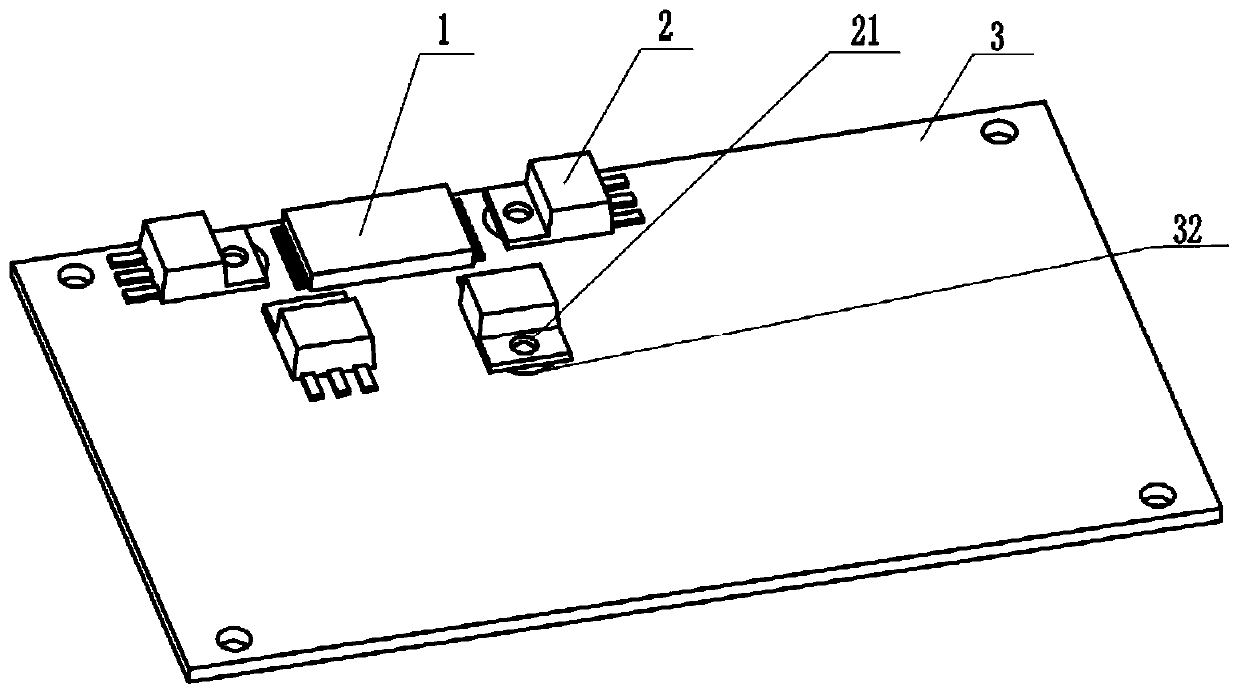
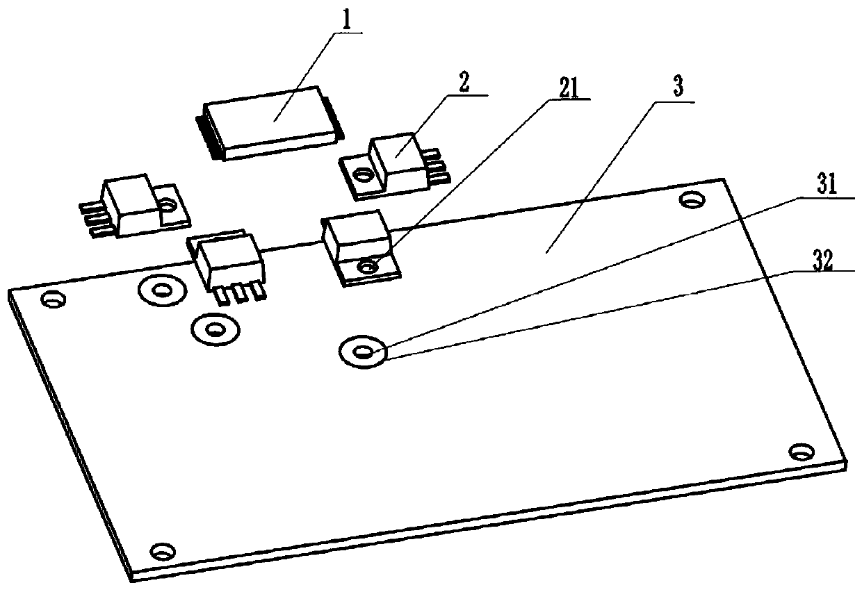
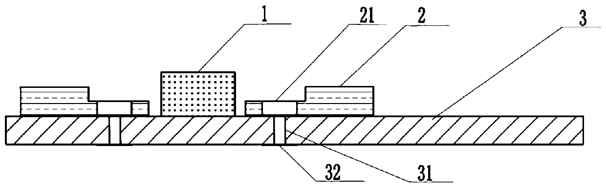
[0026] see Figure 1-Figure 6 , a high-efficiency and low-cost PCB heat dissipation d...


PUM


Abstract

The invention relates to the field of PCB circuits, in particular to a high-efficiency and low-cost PCB heat dissipation device. The high-efficiency and low-cost PCB heat dissipation device comprisesa PCB, a chip and a heating device are arranged on the PCB, a through hole is formed in the PCB, an installation hole is formed in the heating device, and the installation hole and the through hole inthe PCB are concentrically arranged. The invention relates to the high-efficiency and low-cost PCB heat dissipation device, in which the thermal resistance in the heat conduction process is reduced,short-distance efficient heat conduction and radiation to a shell in a small space is realized, the fixing mode of heat dissipation fins is simplified, the mounting difficulty is reduced and the material cost is saved.

Description

technical field [0001] The invention relates to the field of PCB board circuits, in particular to a high-efficiency and low-cost PCB heat dissipation device. Background technique [0002] In a PCB circuit containing heating components such as power tubes, magnetic core devices, and power resistors, the heat dissipation capability directly affects the overall maximum working ambient temperature and product life of the product. Regarding the heat dissipation technology of the PCB board, the currently commonly used methods are: 1) A heat dissipation aluminum sheet is attached to the power tube or the heating magnetic core. In the air, the space temperature is high, which affects the life of electronic devices, and it is not convenient to produce and assemble; 2) Install cooling modules such as cooling fans or water-cooling pipes on the PCB. The disadvantage of this method is that it is troublesome to install and the product cost is high. [0003] To sum up, the traditional hea...

Claims


Application Information

Patent Timeline
Patent Type & Authority Applications(China)
IPC IPC(8): H05K1/02H05K1/18
CPCH05K1/0203H05K1/0206H05K1/021H05K1/18H05K2201/066
Inventor 周江涛田鹏黄海金
Owner HANGZHOU INST OF ADVANCED TECH CHINESE ACAD OF SCI
Why Eureka
Try Eureka