
Electric tool

A technology of electric tools and tools, applied in the direction of striking tools, manufacturing tools, portable impact tools, etc., can solve the problems of reduced work efficiency and increased time lag, and achieve the effect of improving work efficiency

Pending Publication Date: 2020-03-06
HITACHI KOKI CO LTD
View PDF8 Cites 1 Cited by
  • Summary
  • Abstract
  • Description
  • Claims
  • Application Information

AI Technical Summary

Problems solved by technology

Specifically, every time the trigger switch is temporarily turned off and turned on again, control is performed to drive the motor once at a low speed and then increase the speed to a high speed after a load is detected. Therefore, there are the following problems: The time lag from when the trigger switch is turned on again until the motor speed reaches the high speed (actual work speed) increases, and the work efficiency decreases.

Method used


Image

  • Electric tool
  • Electric tool
  • Electric tool

Examples


Embodiment Construction

[0040] Hereinafter, preferred embodiments of the present invention will be described in detail with reference to the drawings. In addition, the same reference numerals are attached to the same or equivalent constituent elements, members, processes, etc. shown in each drawing, and overlapping descriptions are appropriately omitted. Furthermore, the embodiments are illustrative rather than restrictive, and all the features described in the embodiments or combinations thereof are not necessarily the essence of the invention.

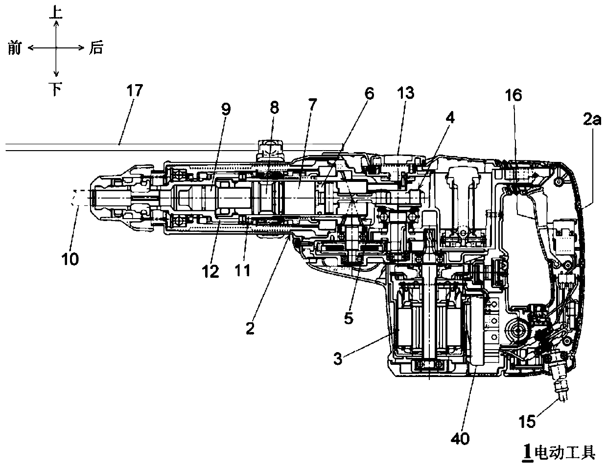
[0041] figure 1 It is a side sectional view of the electric power tool 1 which concerns on embodiment of this invention. pass figure 1 to define the front-back and up-down directions. The electric tool 1 is a percussion drill (percussion machine), and by applying rotational force and impact force to the tip tool 10, it is possible to perform chiseling, drilling, and crushing on workpieces such as concrete and stone. In the electric power tool 1 , the st...


PUM


Abstract

The present invention provides an electric tool with which work efficiency can be improved. A controller (106) of an electric tool (1) can execute: first control, whereby during a non-work state aftera motor (3) has started up and before a tip tool enters a work state, the motor (3) is driven at a slow idling rotation speed, and when the tip tool enters the work state, the motor (3) is driven ata normal rotation speed which is higher than the slow idling rotation speed; and second control, whereby in a case where a trigger switch (16) has been turned off in a state where the motor (3) is being driven at the normal rotation speed and the trigger switch (16) is thereafter turned on again under a prescribed condition, the motor (3) is driven at the normal rotation speed regardless of the state of the tip tool.

Description

technical field [0001] The invention relates to an electric tool such as an impact hammer or an impact drill. Background technique [0002] In electric tools such as impact hammers and impact drills, in order to suppress unnecessary noise or vibration when there is no load, there is known low-speed no-load control in which the motor is controlled to rotate at a low speed when there is no load. When a load is detected, the motor is switched to the desired high speed. [0003] prior art literature [0004] patent documents [0005] Patent Document 1: Japanese Patent Laid-Open No. 2010-173053 Contents of the invention [0006] The problem to be solved by the invention [0007] In the case of frequent switching between the state where the trigger switch is turned on and the motor is driven and the state where the trigger switch is turned off without driving the motor (such as planing and shoveling work using an impact hammer), sometimes due to low-speed no-load control le...

Claims


Application Information

Patent Timeline
IPC IPC(8): B25F5/00B25D16/00B25D17/00
CPCB25F5/00B25D16/006B25D2216/0015B25D2216/0023B25D2250/221B25D2250/131B25D11/005B25D17/11B25D17/24B25D17/00B25D2216/0084B25D2250/095B25D2250/201B25D2250/265
Inventor 山田英贵桥本秀幸野口裕太
Owner HITACHI KOKI CO LTD
Learn More