

Method and formulation for renewable polyethylene foams
A foam, polyolefin technology, used in the field of foam, foam, can solve problems such as reducing physical and mechanical properties
- Summary
- Abstract
- Description
- Claims
- Application Information
AI Technical Summary
Problems solved by technology
Method used
Image

Examples
Embodiment 1
[0070] Example 1: Biobased Carbon Testing of Samples 1 and 2
[0071] To measure percent biobased carbon content, ASTM D6866-16 testing (authorized by ISO / IEC 17025:2005) was performed at Beta Analytic, Inc, Miami, Florida. ASTM D6866-16 cites the definition of biobased, which includes organic carbon from renewable sources such as agricultural, plant, animal, fungal, microbial, marine or forestry materials living in a natural environment in balance with the atmosphere. Thus, the percentage of biobased carbon in a manufactured product most often indicates the amount of non-petroleum derived carbon present. It is calculated and recorded as renewable organic carbon as a percentage of total organic carbon (TOC) present.
[0072] Two analytical methods are described in ASTM D6866-16, Method B (AMS) and Method C (Liquid Scintillation Counting (LSC)). Method B is the most accurate and precise and was used to produce this result. This method uses radiocarbon (also known as C14, car...
Embodiment 2
[0075] Example 2: Method of making renewable foam
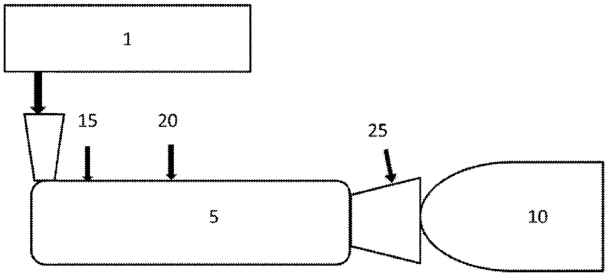
[0076] The renewable foam is produced in an extrusion process. Using renewable LDPE resin from Braskem. Renewable LDPE with 96% C14 content and a density of 0.923g / cm 3 , a melt flow rate of 2.0 at 190 °C and a load of 2.16 kg. It is produced from sugarcane-based ethanol as a feedstock to produce ethylene, which is then polymerized to produce LDPE. Foam cells were nucleated using 50% talc masterbatch in LDPE carrier resin (Polyfil Corporation). Standard glyceryl monostearate (GMS) Kemester 124 flakes supplied by PMC Biogenix were used as an aging modifier to stabilize the cells and isobutane gas was used as a blowing agent to expand the foam.
[0077] figure 1 A schematic diagram of the foam extrusion process is shown. The resin, Braskem SLD 4004 and nucleating agent were fed into the first hopper 1 and into the counter-rotating twin-screw extruder 5 . The aging modifier is fed into the extruder 5 in a second hopper at...
Embodiment 3
[0081] Embodiment 3: drop test
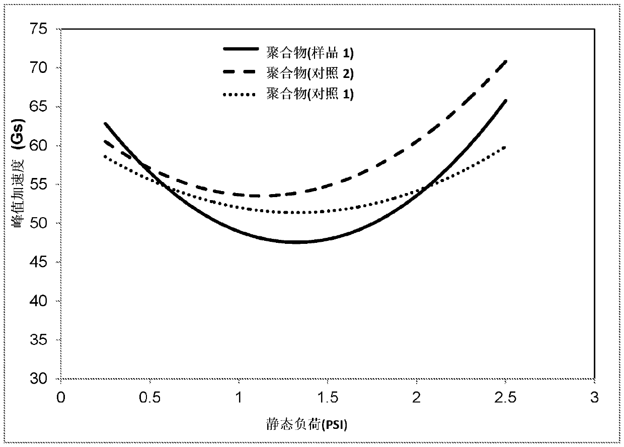
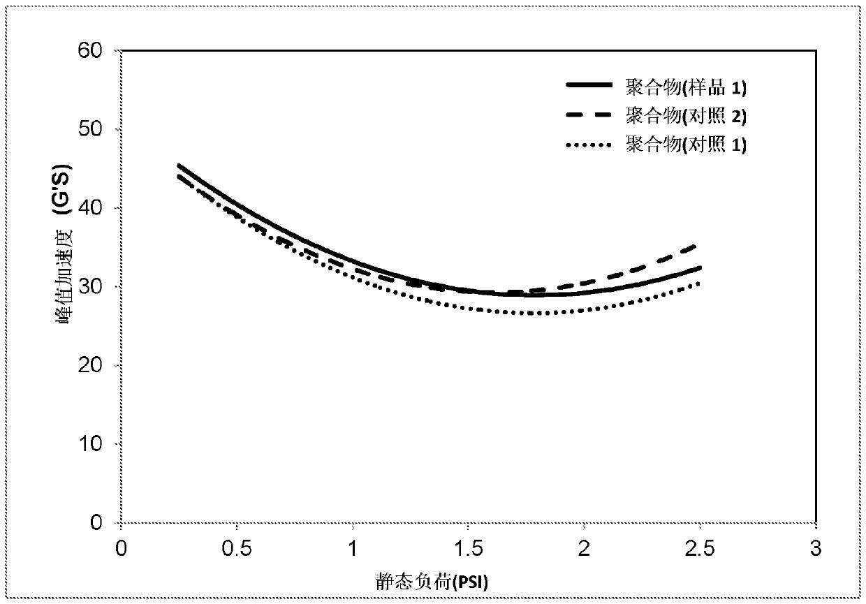
[0082] A drop test was performed to evaluate the transmission impact cushioning of Sample 1. A Lansmont M65 / 81 impact machine was used for the drop test. A test pack was prepared using a test box, a sheet of Sample 1 in the test box, and a static load placed in the voids of the sheet of Sample 1 . The static load was centered and placed around the static load using additional Sample 1 foam. Use additional Sample 1 foam as a cushioning arrangement to fill any remaining empty space in the test pack. Place the test pack under the table, allowing 1.5 inches of room to spring back. Attach an accelerometer and perform drops at different heights. Drop tests were performed at 12 inches, 18 inches, 24 inches, 30 inches and 36 inches. Control 1 and Control 2 shown in Table 2 were also tested under the same conditions for comparison.
[0083] Figure 5-8 The cushioning curves for the above foams at 12", 24", 30" and 36" drop heights are shown respe...
PUM
| Property | Measurement | Unit |
|---|---|---|
| density | aaaaa | aaaaa |
| thickness | aaaaa | aaaaa |
| thickness | aaaaa | aaaaa |
Abstract
Description
Claims
Application Information