
A sand making device

A technology for manufacturing equipment and sand and gravel, which is applied in the field of sand and gravel manufacturing equipment, and can solve problems such as inability to apply processing

Active Publication Date: 2021-02-02
HARBIN UNIV
View PDF1 Cites 0 Cited by
  • Summary
  • Abstract
  • Description
  • Claims
  • Application Information

AI Technical Summary

Problems solved by technology

[0002] For example, the publication number CN108636576A is a grinding machine for gravel processing, which includes a main body, the outer surfaces of both sides of the lower end of the main body are fixed with a main machine base, and the outer surface of the front end side of the main machine base is fixed with a slag spit. The outer surface of the front end of the host main body is fixedly equipped with a working cylinder and a maintenance cylinder, and the working cylinder is located on one side of the maintenance cylinder, and an observation door, an air inlet and a main engine motor are fixedly installed on one side of the outer surface of the host main body. And the observation door is located on one side of the air inlet, and the host motor is located on the other side of the air inlet; the disadvantage of this invention is that different processing conditions cannot be imposed according to different processing sequences

Method used


Image

  • A sand making device
  • A sand making device
  • A sand making device

Examples


specific Embodiment approach 1

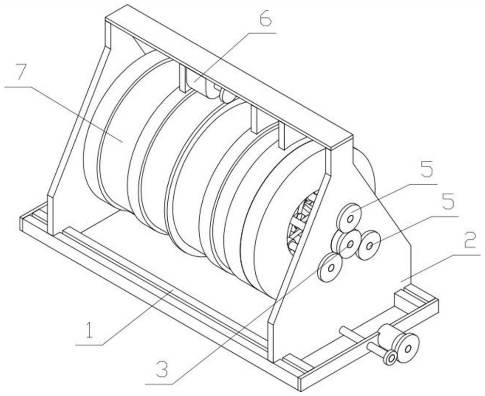
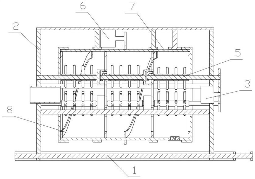
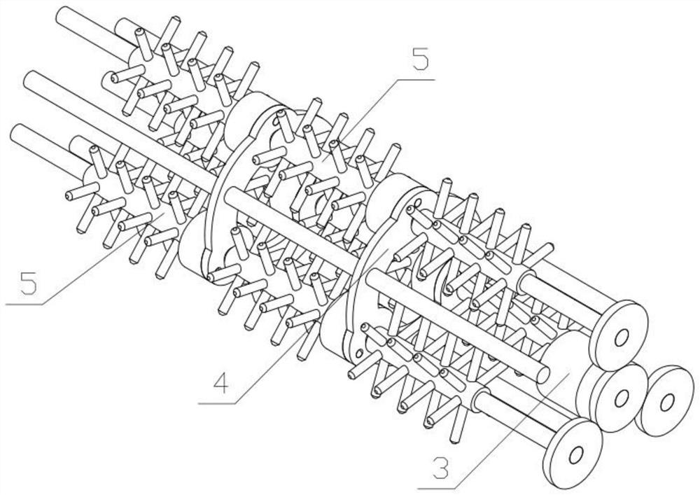
[0033] Combine below Figure 1-11Description of this embodiment, a gravel manufacturing device, including a sliding bracket 1, a device bracket 2, a power motor 3, a rotating bracket 4, a crushing mechanism 5, a rotating motor 6, a crushing cylinder 7 and a pushing mechanism 8, the sliding bracket 1 A device support 2 is connected on the device support 2, a power motor 3 is fixedly connected on the device support 2, a rotating support 4 is fixedly connected on the device support 2, and a plurality of crushing mechanisms 5 are connected in rotation on the device support 2, and a plurality of crushing mechanisms 5 are all connected with the power The motor 3 is meshed and driven, and a plurality of crushing mechanisms 5 are rotatably connected to the rotating bracket 4, the rotating motor 6 is fixedly connected to the device bracket 2, and the crushing cylinder 7 is rotatably connected to the device bracket 2, and the crushing cylinder 7 and the rotating motor 6 are meshed for tr...

specific Embodiment approach 2

[0035] Combine below Figure 1-11 Describe this embodiment, this embodiment will further explain the first embodiment, the sliding bracket 1 includes a sliding track 1-1, a connecting plate I1-2, a reciprocating screw rod 1-3 and a reciprocating motor 1-4, the sliding track 1- 1 There are two, the front and rear ends of the two slide rails 1-1 are fixedly connected with connecting plates I1-2, and the two connecting plates I1-2 are connected with reciprocating screw rods 1-3 in rotation, one side A reciprocating motor 1-4 is fixedly connected to the connecting plate I1-2, and the reciprocating motor 1-4 and the reciprocating screw mandrel 1-3 are transmission connected.

specific Embodiment approach 3

[0037] Combine below Figure 1-11 Describe this embodiment, this embodiment will further explain the second embodiment, the device bracket 2 includes a support plate I2-1, a connecting plate II2-2, a support plate II2-3, a feeding cylinder 2-4, and an installation ring I2 -5. Blocking the arc plate 2-6 and the arc hole 2-7, there are two supporting plates I2-1, and the upper ends of the two supporting plates I2-1 are fixedly connected with the connecting plate II2-2, the connecting plate The lower end of II2-2 is fixedly connected with the installation ring I2-5, the front side of the lower end of the connection plate II2-2 is fixedly connected with the blocking arc plate 2-6, and the lower end of the blocking arc plate 2-6 is provided with an arc hole 2- 7. The feeding cylinder 2-4 is fixedly connected to the support plate Ⅱ2-3 on the rear side, and the left and right sides of the two support plates Ⅰ2-1 are respectively slidably connected to the two sliding rails 1-1. The tw...


PUM


Abstract

The invention relates to a manufacturing device, more specifically a sand and gravel manufacturing device, including a sliding bracket, a device bracket, a power motor, a rotating bracket, a crushing mechanism, a rotating motor, a crushing cylinder and a pushing mechanism, which can drive multiple The crushing mechanism rotates, and multiple crushing mechanisms crush the stones in the crushing barrel. There are multiple pushing areas on the pushing mechanism. The pushing speed of each pushing area is different. The crushing mechanism is equipped with multiple crushing areas. Each crushing area The torque is different, and the multiple pushing areas correspond to the multiple crushing areas. The stone first passes through the crushing area with a large torque and the slow pushing area to ensure that large stones can be completely crushed, ensuring the crushing effect, and the torque in the crushing area. Decrease in turn, and the pushing speed in the pushing area will increase in turn to ensure the processing speed of the stone.

Description

technical field [0001] The invention relates to a manufacturing device, in particular to a sandstone manufacturing device. Background technique [0002] For example, the publication number CN108636576A is a grinding machine for gravel processing, which includes a main body, the outer surfaces of both sides of the lower end of the main body are fixed with a main machine base, and the outer surface of the front end side of the main machine base is fixed with a slag spit. The outer surface of the front end of the host main body is fixedly equipped with a working cylinder and a maintenance cylinder, and the working cylinder is located on one side of the maintenance cylinder, and an observation door, an air inlet and a main engine motor are fixedly installed on one side of the outer surface of the host main body. And the observation door is located on one side of the air inlet, and the main machine motor is located on the other side of the air inlet; the disadvantage of this inve...

Claims


Application Information

Patent Timeline
Patent Type & Authority Patents(China)
IPC IPC(8): B02C13/06B02C13/30B02C13/28B02C13/26
CPCB02C13/06B02C13/26B02C13/2804B02C13/30
Inventor 王琼马玉秋陈刚董如国
Owner HARBIN UNIV
Learn More